Connections – Panasonic GP-MS112 User Manual
Page 7
Attention! The text in this document has been recognized automatically. To view the original document, you can use the "Original mode".
CONNECTIONS
Caution:
1,
Keep the Power ON/OFF Switch in the OFF position
until ail connections have been properly made.
2.
Connect the camera head and camera control unit
which are packed in the same box (a pair) otherwise it
would cause a improper operation.
• Internal Sync Operation
1. Connect the camera cable with 12-pin connector of
the camera head to the Camera Cable Connector (7)
on the front panel of the camera control unit.
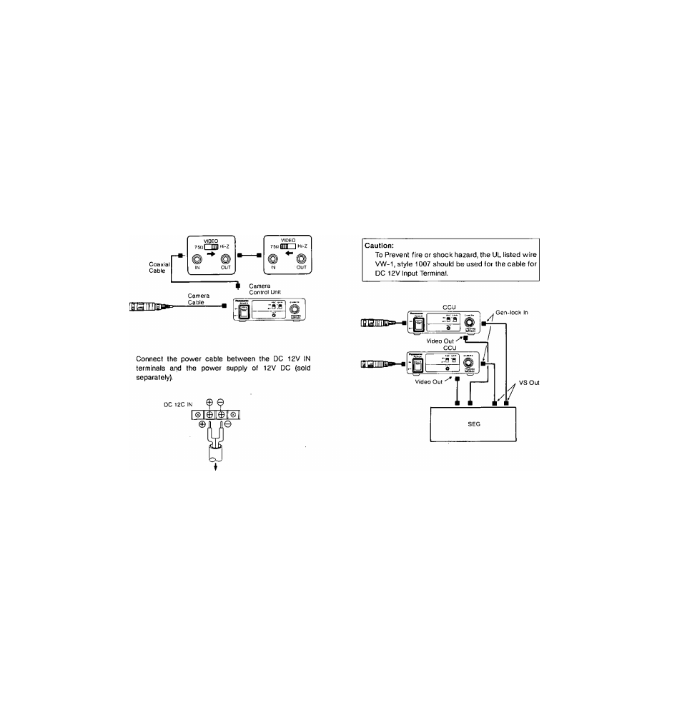
• Gen-lock Operation
1.
Connect the camera cable with 12-pin connector of
the camera head to the Camera Cable Connector (7)
on the front panel of the camera control unit.
2.
Connect the coaxial cables with BNC connectors
between the Video Output connector (11) of camera
' control unit and the Video Input of Special Effects
Generator and between the VS Output connector of
SEG and the Gen-Lock Input connector of camera
control unit.
2. Connect the coaxial cable with BNC connectors
between the Video Output connector (11) of the camera
control unit and the video monitor or VTR.
3.
Connect the power cable between the DC 12V IN
terminals and the Power Supply of 12V DC (sold
separately).
Video
Monitor
VTR or
Video Monitor
CAUTION: CONNECT THIS TO A DC 12V CLASS 2
POWER SUPPLY ONLY.
■fi2V DC Power Supply
CAUTION: CONNECT THIS TO A DC 12V CLASS 2
POWER SUPPLY ONLY.
Caution:
To Prevent fire or shock hazard, the UL listed wire
VW-1, style 1007 should be used for the cable for
DC 12V Input Terminal.
- 6 -