Cabletron Systems Expansion module 9H532-17 User Manual
Page 34
LANVIEW LEDs
4-2
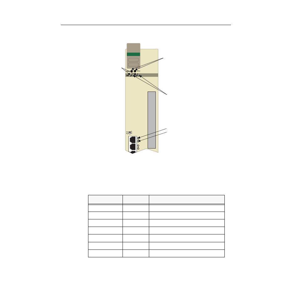
Figure 4-1. The LANVIEW LEDs (9H532-17 shown) and LED Mode Switch
The functions of the two System Status LEDs, System Management Bus (SMB)
and the CPU, are listed in Table 4-1.
Table 4-1. System Status (SMB and CPU) LEDs
LED Color
State
Description
Green
Functional
Fully operational
Yellow
Testing
Power-up testing
Yellow (Flashing)
Crippled
Not fully operational (e.g., one bad port)
Yellow/Green
Booting
Blinks yellow and green while booting
Red
Reset
Normal power-up reset
Red (Flashing)
Failed
Fatal error has occurred
Off
Power off
Module powered off
FAST ENET
9H532-17
16
15
System Status
INB Transmit
INB Receive
Port Receive
Port Transmit
This manual is related to the following products: