I keyboard stand assembly, Zusammenbau des keyboard- ständers und aufstellung, Keyboard stand assembly – Yamaha CLP-350 User Manual
Page 4: G g g g
Attention! The text in this document has been recognized automatically. To view the original document, you can use the "Original mode".
1
A-
B
é
g g g g
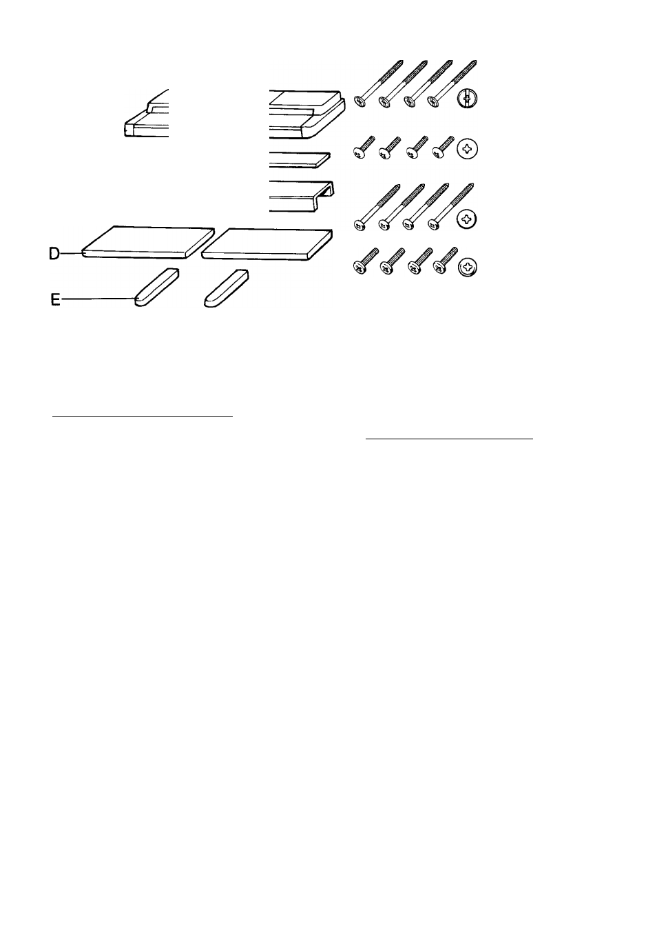
►Long screws (black) x 4
►Lange Schrauben (schwarz) x 4
►Vis longues (noires) x 4
►Tornillos largos (negros) x 4
►Short large-head screws
(black) X 4
►Kurze Schrauben mit großem
Kopf (schwarz) x 4
►Vis courtes à grosse tête
(noires) X 4
►Tornillos cortos de cabeza
grande (negros) x 4
►Long screws (gold) x 4
•Lange Schrauben (goldfarben) x
►Vis longues (dorées) x 4
►Tornillos largos (dorados) x 4
♦Short screws (black) x 4
•Kurze Schrauben (schwarz) x 4
•Vis courtes (noires) x 4
•Tornillos cortos (negros) x 4
•Joint connectors x 8
•Verbindungsstücke X 8
•Dispositifs d'assemblage X 8
•Juntas X 8
I Keyboard Stand Assembly
I
Open the box and remove all the parts.
On opening the box you should find the parts shown
in the illustration to the above. Check to make sure
that all the required parts are provided.
Assemble the side panels (D) and base boards
(E).
Install the joint connectors in side panels (D) as
shown in the illustration, then secure the base boards
(E) to the side panels (D) with the long gold-colored
screws.
* When installing the joint connectors in the holes in
the side panels (D), make sure that the arrows printed
on their upper surface face in the direction shown in
the illustration.
* Make sure that the left and right base boards are
facing in the proper direction as shown in the illustra
tion. The grooved edge of each base board should
face inward.
Attach the side panels (D) to the pedal box (C).
Place the pedal box on top of the brackets attached
to the side panels (D), and attach using the four
short large-head black-colored screws.
Attach the rear panel (B) to the side panels (D).
Insert four joint connectors into the four holes at
the rear side of the rear panel (B) (two holes on each
side). Then secure the rear panel (B) to the side panels
(D) using the four long black-colored screws.
* When installing the joint connectors in the holes in
the rear panel (B), make sure that the arrows printed
on their upper surface face in the direction shown in
the illustration.
Zusammenbau
des
Keyboard-
Ständers und Aufstellung
1
Den Versandkarton öffnen und alle Teile
auspacken.
Der Versandkarton sollte alle oben gezeigten Teile
enthalten. Sicher stellen, daß alle benötigten Teile
vorhanden sind.
Die Seitenplatten (D) und Füße (E) zusammen
bauen.
Die Verbindungsstücke entsprechend der Abbildung
in die Seitenplatten (D) einsetzen. Dann die Füße
(E) mit den langen goldfarbenen Schrauben an den
Seitenplatten (D) anbringen.
* Beim Einsetzen der Verbindungsstücke in die Bohrungen
der Seitenplatten (D) sicherstellen, daß die Pfeile auf
den Oberseiten wie in der Abbildung ausgerichtet sind.
* Sicherstellen, daß linker und rechter Füß in die in der
Abbildung gezeigten Richtung weisen. Die Füß mit der
Nut sollte dabei nach innen weisen.
Die Seitenplatten (D) an der Pedalkonsole (C)
anbringen.
Die Pedalkonsole auf die Halterungen an den Seiten
platten (D) aufsetzen und durch Eindrehen der vier
kurzen schwarzen Schrauben mit großem Kopf
befestigen.
Die Rückwand (B) an den Seitenplatten (D)
anschrauben.
Die vier Verbindungsstücke in die vier Löcher der
Rückwand (B) (zwei Löcher auf jeder Seite) einsetzen
und dann die Rückwand (B) mit den vier langen
schwarzen Schrauben an den Seitenplatten (D)
anschrauben.
* Beim Einsetzen der Verbindungsstücke in die Bohrungen
der Rückwand (B) sicherstellen, daß die Pfeile auf den
Oberseiten wie in der Abbildung ausgerichtet sind.