Interface parameters, Software parameters, Pin assignment of the d-sub connector – Leica Geosystems Leica DISTO OEM Module 3.0 WH15/WH30 User Manual
Page 5: Technical reference manual, Disto
Technical Reference Manual
V1.20
5/12
725538.doc
08.11.01
DISTO
DISTO
DISTO
DISTO
TM
TM
TM
TM
OEM module 3.0 WH15/WH30
OEM module 3.0 WH15/WH30
OEM module 3.0 WH15/WH30
OEM module 3.0 WH15/WH30
3. Interface parameters
3.1. Software parameters
The interface of the DISTO
TM
OEM module 3.0 has been arranged so that it can be connected to a PC by means
of an adapter. The parameters of the interface are defined ex-works as follows:
9600 baud, none parity, 8 data bits, 1 stop bit
These settings can be changed, using the interface commands.
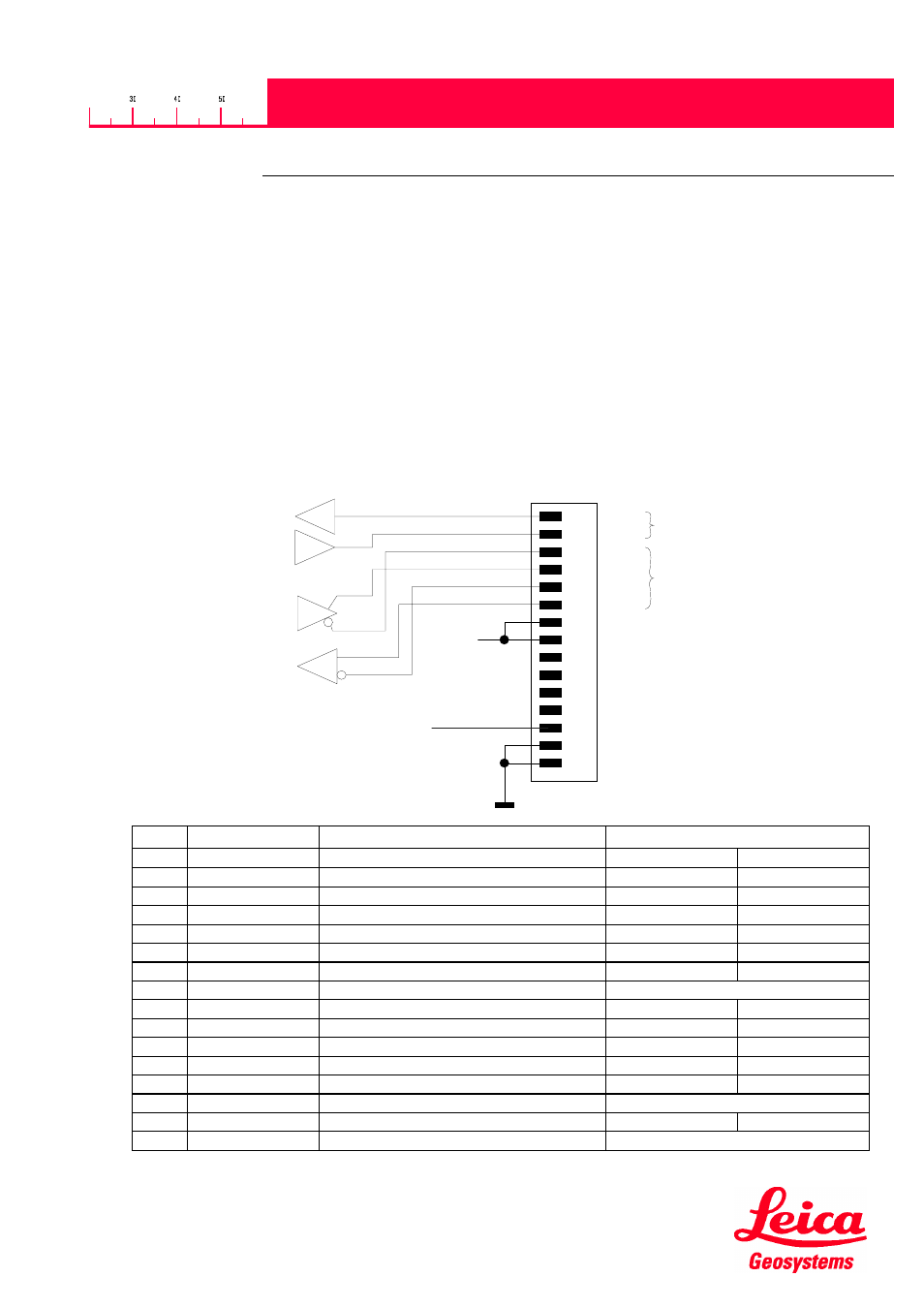
3.2. Pin assignment of the D-sub connector
The 15 pin D-sub connector contains the lines for RS232, RS422 and the power.
1
2
5
4
3
8
7
6
11
10
9
14
13
12
15
VCC
RX
TX
-RI
+DO
-DO
9..30VDC
+RI
GND
RS232
RS422
ON/OFF
Pin
Designator
Description
Colors for accessories cable
725005 (RS422)
725006 (RS232)
1
RS232 Tx
RS232 Send line
White
2
RS232 Rx
RS232 Receive line
Brown
3
-DO
RS422 Send line negative
White
4
+DO
RS422 Send line positive
Brown
5
-RO
RS422 Receive line negative
Green
6
+RO
RS422 Receive line positive
Yellow
7
BAT +
Power DC +9V…+30V
Brown (Supply cable)
8
BAT +
Power DC +9V…+30V
9
NC
10
NC
11
NC
12
NC
13
ON / OFF
ON: Open OFF: switch to ground
Green (Supply cable)
14
GND
Ground line
Grey
Green
15
GND
Ground line
White (Supply cable)