Operation, 1 led indicators – CANOGA PERKINS 9119 Rack Mount 100BASE-TX/FX Media Converter User Manual
Page 17
17
9119 Media Converter
Canoga Perkins
3. Operation
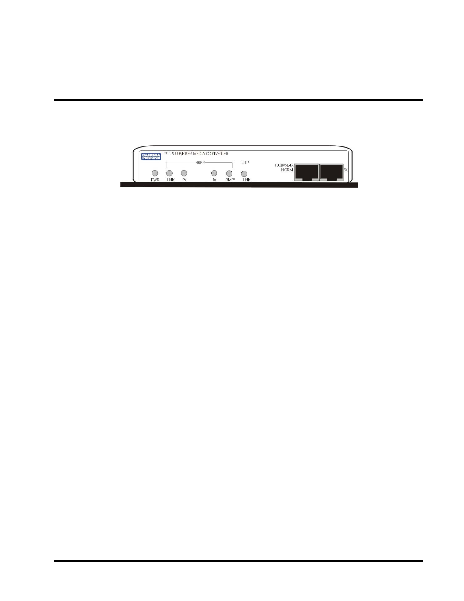
Figure 3-1
9119 LED Indicators
PWR
Power Indicator (Green)
When lit, PWR indicates that the unit is receiving power.
LNK
Fiber/Interface Integrity Indicator
(Fiber) (Green)
When lit, LNK indicates that sufficient modulated light energy is being received by the Fiber interface.
When this indicator turns off, the 9119 Media Converter will transmit a Remote Fault to the remote fiber optic
interface, and through LLF, will disable its local UTP transmitter, causing a loss of Interface Integrity at the local
UTP device.
Rx
Receive Data, Fiber to UTP (Green)
When lit, Rx indicates that the converter is receiving packets via the fiber optic cable.
Tx
Transmit Data, UTP to Fiber (Green)
When lit, Tx indicates that the converter is receiving packets via the UTP cable and is attempting to transmit them
via the fiber optic cable.
RMTF Remote Fault (Red)
Remote Fault Indication (RMTF) is a featurethat is complimentary to LLF. It is essentially a means by which error
conditions are echoed back to the unit that is potentially causing errors. Upon loss of link integrity on a fiber
optic port, the remote device transmits an RMTF pulse from its Tx port to the local device, indicating an error
condition on the Tx port or that the fiber optic link may have failed.
This feature allows the local unit to become "aware" of fault conditions that it is possibly creating. Upon receipt of
the RMTF signal, the local unit, be it a 9119, 9135, or 9140, will illuminate the RMTF Indicator and invoke LLF
on the local interface.
NOTE: The following additional effects may also be generated by the receiving device, depending upon the equipment and
configuration:
•
9119s will close dry relay alarm contacts reserved for RMTF.
•
LLF on the UTP port will propagate the failed condition to the attached DTE device.
•
Non-managed 9135/9140s, when LLF is enabled on the 100BASE-FX interface will also propagate the
failure condition to the attached DTE device.
•
Managed 9135/9140s generate TRAP 43 "remote fault on port 2" both in-band and out-of-band via SLIP
port if so configured (and dry relay contact closure).
3.1 LED Indicators
The 9119 Media Converter has six LED indicators on the front panel (see Figure 3-1).