Display adjust mode – BendixKing CNI 5000 User Manual
Page 15
14
then be selected to “ON” or “ALT” on the
ground, but will continue to annunciate
“GND” and only accept Mode S interroga-
tions. Once the aircraft is airborne and the
strut switch relaxes, the unit automatically
annunciates the selected mode and oper-
ates accordingly. This feature eliminates
the possibility of taking off and forgetting to
activate the Mode A/C capability of the
transponder.
ON- The unit is able to reply to all valid
Mode A, Mode C and Mode S interroga-
tions, however; the altitude information of
Mode C reply and the altitude fields of the
Mode S replies are suppressed. The alti-
tude display is blank and the ID 4096 code
is displayed on the right. “ON” is annunci-
ated on the display in this mode.
ALT- The unit is able to reply to all valid
Mode A, Mode C and Mode S interroga-
tions. The altitude information will be sent
in Mode C and the altitude field of Mode S
replies. The ID 4096 code will be display
on the right and the altitude will be dis-
played on the left (in hundreds of feet).
XPDR 1 / XPDR 2 SWITCH
Since only one transponder can be active
at a time, the XPDR 1/2 switch is used to
select which transponder is active. In addi-
tion to providing quick access to a backup
system, the XPDR 1/2 switch can also act
as a virtual “flip-flop” similar to that on the
COMM, NAV and ADF.
With XPDR 2 set for the VFR code,
and XPDR 1 set to the last ATC-assigned
squawk code, toggling the XPDR 1/2 switch
automatically activates the selected transpon-
der while simultaneously putting the other
transponder in standby (even when the func-
tion switch is selected to an active mode).
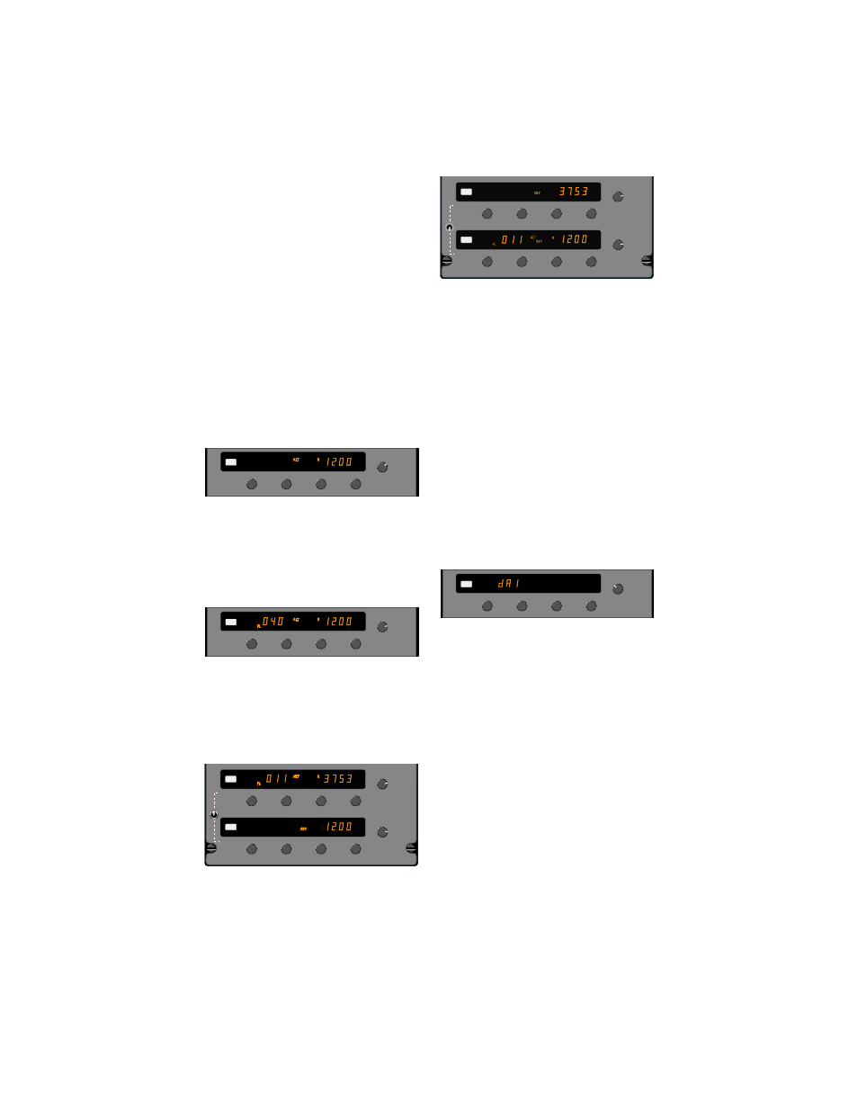
DISPLAY ADJUST MODE
The display has 3 programmable adjust-
ments. The first (dA 1) is for the response
time for dimming, the second (dA 2) is to set
the display for minimum brightness, and the
third (dA 3) is to compensate brightness for
different vendors and/or aging of the display.
To enter the Display Adjust Mode, per-
form the following steps:
1. Turn the function selector knob to TST.
2. Press and hold the “IDT” button for five
seconds until “dA1” appears in the altitude
window.
3. Select the desired display adjustment by
depressing the “VFR” pushbutton.
(Select dA1, dA2, or dA3).
4. Set the proper adjustment value in the
IDENT window with the far right Ident
Code Selector Knob.
MODE
RANGE
DESCRIPTION
dA1
1 to 8
Photocell response
(1=fast, 8=slow).
(Normal= 1)
dA2
0 to 64
Display brightness
(0=dim, 64=bright)
(Normal= 20)
dA3
0 to 255
Vendor/Age comp.
(0=dim, 255=bright)
(Normal= 0)
5. Press the “IDT” pushbutton or turn the
Function Selector knob to exit the display
adjust mode and save the new values.
FL
XPDR 1
PUSH
VFR
SBY
OFF
GND
TST
ON
ALT
300
IDT
XPDR 1
PUSH
VFR
SBY
OFF
GND
TST
ON
ALT
ALT ON
GND SBY
R
1200
IDT
FL
XPDR 1
PUSH
VFR
SBY
OFF
GND
TST
ON
ALT
IDT
SBY
OFF
GND
TST
ON
ALT
XPDR 1
XPDR 2
PUSH
VFR
PUSH
VFR
SBY
OFF
GND
TST
ON
ALT
FL
IDT
R
071
IDT
SBY
ALT ON
ON
GND
GND
SBY
OFF
GND
TST
ON
ALT
XPDR 1
XPDR 2
PUSH
VFR
PUSH
VFR
SBY
OFF
GND
TST
ON
ALT
IDT
IDT
ON
ON
GND
GND
FL
ALT
R
011