Vernier Digital Control User Manual
Page 5
9
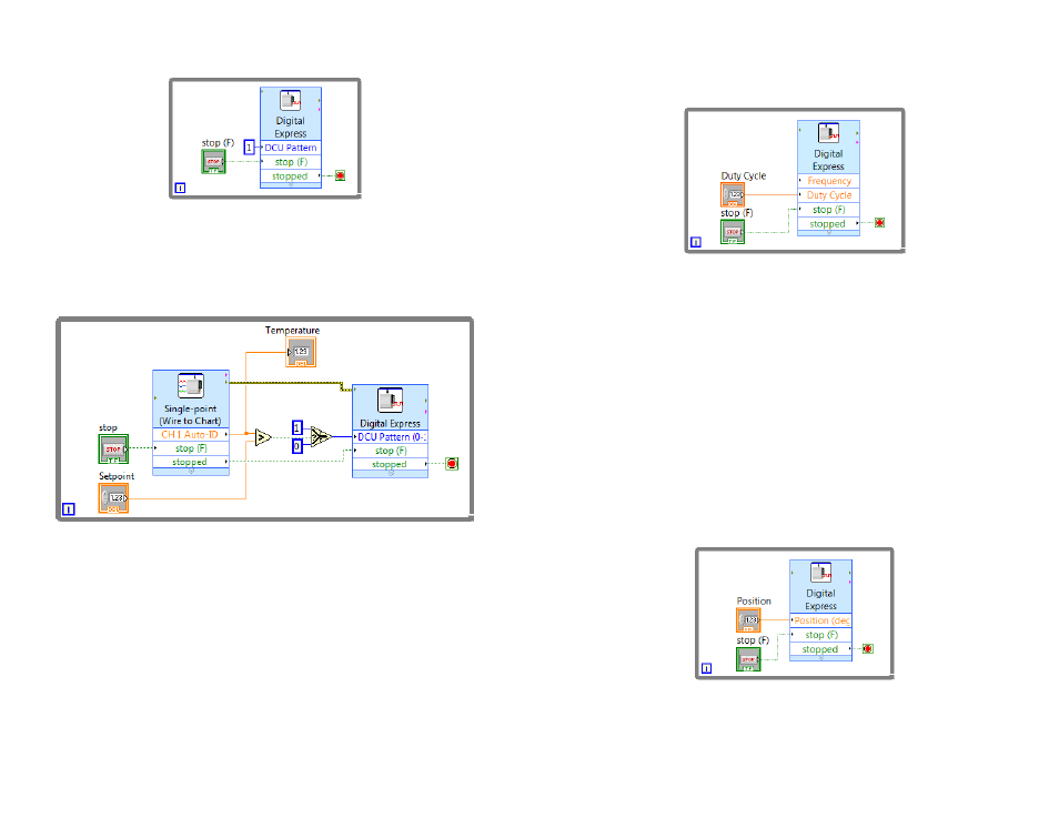
The DCU Pattern is an input terminal on the Digital Express VI and can be
programmed as a constant, as shown in Figure 8, or as a front-panel control, as
shown in Figure 9, depending upon your application.
Figure 8 LabVIEW VI to control a DCU line
Alternatively, the DCU Pattern can be controlled from sensors connected to the
system to create the same examples as described in the Logger Pro Examples section
of this manual. A simple example program for a temperature monitoring system is
shown in Figure 9. In this program, an Analog Express VI is used to collect data
from a temperature sensor connected to the interface. DCU line D1 will turn on
when the temperature exceeds a set point defined by a front-panel control.
Figure 9 LabVIEW VI to control the DCU with a sensor reading
It is important when using the Digital Express VI to control a DCU output line that
the “stop (F)” and “stopped” terminals are wired as shown in Figures 8 and 9. This
ensures that all lines are turned off when program execution ends. Avoid using the
Abort Execution button when running your program as it will most likely leave one
or more DCU lines on.
Pulse Train Generation
The DCU can generate pulse trains using LabVIEW. Pulse trains make a digital
controller act like an analog controller by sending a variable voltage signal. This is
called pulse-width modulation (PWM). One common application is a variable speed
control for a DC motor.
The DCU has the ability to generate a pulse train from output line D1 when the DCU
is connected to a SensorDAQ, or output line D4 when the DCU is connected to a
10
LabQuest interface. Users must connect their projects to the correct DCU line when
using the pulse train feature.
In the Digital Express VI configuration window, the duty cycle is a decimal number
between 0 and 1, and indicates the ratio of “on” time to total time. An example of
generating a pulse train is shown in Figure 10.
Figure 10 LabVIEW VI to generate a pulse train
Servo Motors
Another use of PWM is to control a servo motor. The shaft of the servo motor is
oriented to specific angular positions within a ±90° range by sending the servo a
square wave voltage pattern. The shaft position is controlled by the length of time
that the square wave is at the high voltage. The servo motor will hold its position
firmly as long as the square wave continues. The neutral position, (0.5 duty cycle)
corresponds to 0°.
In order to use the Digital Express VI with a servo motor, the control line of the
servo motor must be wired to DCU line D1 if using a SensorDAQ, or DCU line D4
if using a LabQuest. In the Digital Express VI, the default values for the Servo
Pulse-Width Parameters are set for the most commonly used servo motors. These
values can be modified, if necessary, to match the manufacturer’s specifications.
The Digital Express VI must be placed in a While Loop when you are controlling a
servo motor because the pulse train must be sent continuously for the motor to
maintain the desired position. Using a front-panel control to adjust the position of the
motor will make your program more user-friendly.
Figure 11 LabVIEW VI to control the position of a servo motor
Stepper Motors
A stepper motor is a motor that rotates in discrete (individual) steps rather than
continuous movement. It is used in cases where exact control and positioning of a
motion are required.