Vernier Digital Control User Manual
Page 2
3
Whichever option you choose to connect your device to the DCU, you must insulate
the metal leads on all components so that they cannot accidentally touch each other.
The DCU also includes a third connection option: a cluster of three pins providing
connections to the power supply, ground, and line D4. This facilitates connection to
many servo motors. Servo motors require pulse width modulation (PWM) digital
output that can only be used with LabVIEW software.
Table 2
Pin DCU
line
1 D1
2 D2
3 D3
4 D4
5 D5
6 D6
7 XP
8 GND
What can you connect to the DCU outputs?
In general, you can connect any electrical device that runs on DC electricity at a
voltage that matches your power supply. The DCU output voltage can range from 5
to 12 volts, as shown in Table 1. You can find thousands of different 5 to 12 volt
devices at most hobby and electronic stores, such as Mouser, DigiKey, or
Radio Shack.
One common application is using the DCU to turn on an electronic device when a
sensor reading reaches a threshold value. For example, the circuit in Figure 2 shows
a small 5 volt hobby fan connected between the D1 and GND lines of the DCU. If
the temperature reading of a sensor connected to the interface gets too hot, you
would like the fan to automatically turn on just like the air conditioning system in
your home. Conversely, when the temperature cools down, you would like the fan to
turn off. The DCU gives you this on/off control.
Figure 2 Wiring diagram for connecting a fan to the DCU
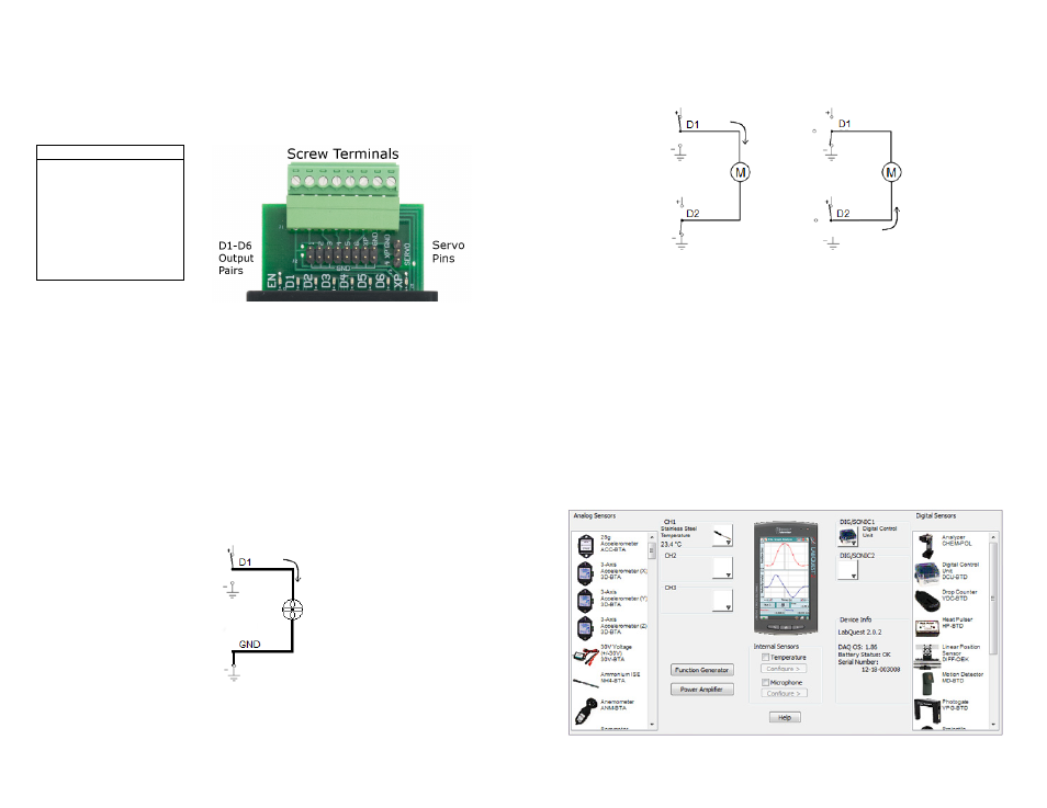
Sometimes you would like to use an electronic device that has the ability to operate
in two different directions. Pairs of DCU lines can be used together to allow you to
switch the polarity or direction of current flow in your device. Consider the circuits
Figure 1 DCU output connectors
4
shown in Figure 3 of a motor wired between the D1 and D2 lines of the DCU. The
circuit on the left has D1 turned on and D2 turned off, so current will flow from D1
to D2 causing the motor to spin in a clockwise direction. The circuit on the right has
D1 turned off and D2 turned on, so current will flow from D2 to D1 causing the
motor to spin in the opposite direction.
Figure 3 Wiring diagram for running a motor in two directions
Using the DCU with Logger Pro
Logger Pro is Vernier’s data-collection and analysis program. The Logger Pro
Digital Out feature allows you to control up to three output lines of a DCU
connected to the DIG 1 or DIG 2 port of a LabQuest or LabPro. Each of the three
lines can be individually controlled based on user-configured conditional statements.
This allows you to develop projects that turn DC motors, lamps, LEDs, buzzers, and
other DC electrical devices on and off based on sensor readings, time, or calculated
columns.
Note: Logger Pro does not support the SensorDAQ interface. To use the Vernier
SensorDAQ with a DCU, you must use LabVIEW software.
Setting up the DCU in Logger Pro
1. Connect the DCU and at least one other Vernier sensor to the data-collection
interface.
2. Choose Set Up Sensors from the Experiment menu and select your interface.
Figure 4 Logger Pro sensor setup window