Vernier Digital Control User Manual
Page 4
7
Note: The Digital Out feature is unable to scan all data at fast data-collection rates.
This may mean that peaks or valleys that fall above or below the user-defined
comparison value, but are of very short duration, might not activate or deactivate a
line as configured. In such a case, LabVIEW provides higher rates and response
times.
Logger Pro Examples
Example 1 Hand Dryer
Set a line controlling a fan to come on if the position reading from a motion detector
is below a threshold (detects the presence of someone’s hands).
Example 2 Night Watering System
Set a line controlling a pump to water your plant if ambient light is below a threshold
value AND the water content of the soil is below a threshold value.
Example 3 Incubator Alarm
Set a line driving a buzzer to go on if a temperature is below a threshold value OR
the temperature is above a second threshold value.
Example 4 Heater with a Dead Zone
Set a line controlling a heater to come on if the temperature is below a threshold
value. The heater stays on UNTIL the temperature goes above a second threshold
value. In this example, using the compound logic operator UNTIL keeps the heater
from rapidly cycling on and off as it would if the temperature simply rose and fell
about a single threshold value.
Example 5 Drinking Fountain
Set a line controlling a fountain to turn on if a person’s position from the fountain is
less than a threshold (they are close) AND the velocity of the person is less than a
threshold (they have stopped moving toward the fountain).
Example 6 Flashing Temperature Alarm
Set a line driving an LED to come on if the temperature is above a set point AND a
calculated column defined by
modulo(integer(3*"Time"), 2)
has a value above 0.5.
The modulo(x,y) function gives the remainder when x is divided by y. In this case,
y=2 so the remainder of any integer is either 0 or 1. If the remainder is 1, the line and
LED comes on; if the remainder is 0, the LED goes off. The speed of the flash is set
by the size of the multiplier inside the integer() function. The value of 3 means the
LED will cycle about 3 times per second.
For more Logger Pro DCU examples, see www.vernier.com/engineering/stem
Using the DCU with LabVIEW Software
LabVIEW is a graphical programming language developed by National Instruments
for creating sophisticated measurement and automation systems. Vernier supports
the use of the Vernier DCU and sensors with LabVIEW version 9.0 or newer. A
package of Express VI’s and a variety of examples for the Vernier SensorDAQ and
all versions of LabQuest interfaces can be downloaded from
www.vernier.com/engineering/ni-labview/downloads
We designed a Digital Express VI (found in the Vernier functions palette) to
simplify the use of the DCU for four application areas: direct control of six output
lines, pulse train generation, and control of servo and stepper motors. The first time
you connect the DCU to the interface, you may notice one or more red LEDs are
8
illuminated. This depends on the interface, the current state of the digital channel,
and/or the model of your DCU. When you set up the DCU in LabVIEW or run a VI
for the first time, all DCU lines should initialize to the off position.
Controlling a Digital Output Line
Direct control of the six digital output lines, D1–D6, is the most commonly chosen
configuration when using the DCU. The line can be connected to the positive side of
the DCU power supply, to the negative side of the power supply, or left
unconnected. If a device is connected from one of the digital lines to ground and the
program directs control to the + position, current will flow and the device will be on.
Either of the other two positions will turn the device off.
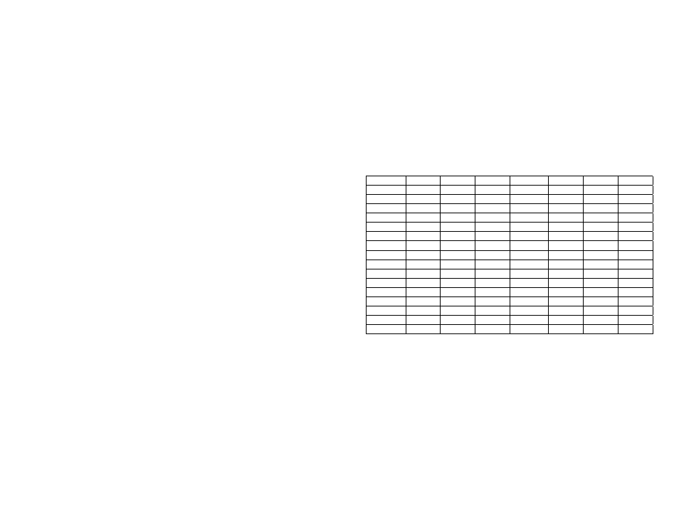
We have developed a table of 16 patterns that allow you independent control of the
first three lines, D1–D3, and limited control of the remaining three lines, D3–D6.
Notice that the first 12 patterns in the table, Patterns 0–11, can be considered the
binary equivalent of the pattern number.
Table 3 DCU Output Patterns
Pattern
Binary
D1 D2 D3 D4 D5 D6
0 0000 −
−
−
− x x
1 0001 + −
−
− x x
2 0010 − + −
− x x
3 0011 + + −
− x x
4 0100 −
− + − x x
5 0101 + − + − x x
6 0110 − + + − x x
7 0111 + + + − x x
8 1000 −
−
− + x x
9 1001 + −
− + x x
10 1010 − + − + x x
11 1011 + + − + x x
12 1100 x x x x −
−
13 1101 x x x x + −
14 1110 x x x x − +
15 1111 x x x x + +
+
indicates the line is connected to the positive side of the DCU power supply
−
indicates the line is connected to the negative side of the DCU power supply
x
indicates the line is disconnected
You can test the 16 different patterns within the configuration window of the Digital
Express VI. To do this, click the increment/decrement button next to the DCU
pattern to see the LEDs illuminate on the graphical display. For example,
configuring a DCU for Pattern 3 means that digital lines D1 and D2 will be turned
on simultaneously. If the DCU is connected to the interface, click Run to activate
these lines on your hardware.
You are given the option of having the lines stay on indefinitely or for a fixed length
of time. Choosing to keep the lines on indefinitely allows you to place the
Express VI within a loop and continuously update the lines as needed.