Vernier Digital Control User Manual
Page 3
5
Note: Some Digital Control Units are not auto-ID. If your DCU has not been
identified by Logger Pro and therefore does not show up under the DIG/SONIC
button, you will need to set it up manually. To do this, click on the DIG/SONIC
button and select Choose Sensor ► Digital Control Unit.
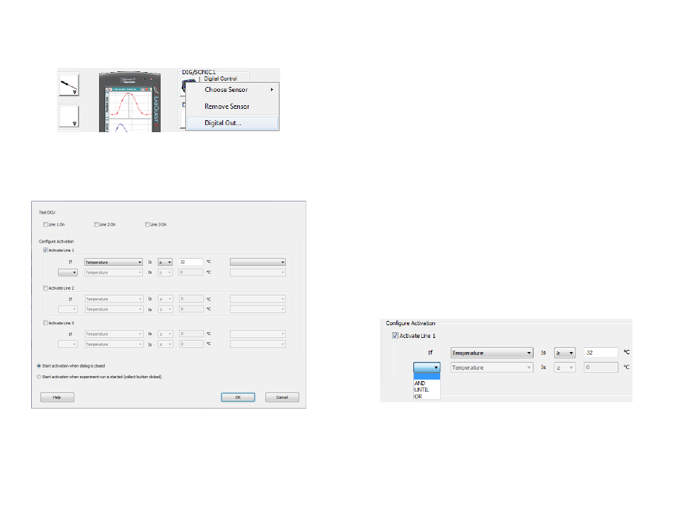
3. Click the DIG/SONIC button and select Digital Out from the drop-down menu.
Figure 5 Digital port drop-down menu in Logger Pro
Use the options in the Digital Out dialog box to configure your DCU output lines
to activate if the condition being evaluated is true. For more information about the
configuration options, see the following section, “Configuring the DCU
Activation in Logger Pro.”
Configuring the DCU Activation in Logger Pro
Figure 6 Digital Out dialog box
You can test the 3 output lines of the DCU by selecting the check box for Line 1
On, Line 2 On, and/or Line 3 On. The LEDs on the circuit board extending from
the DCU will turn on when the line is on. This is a good way to test that your DCU
and electrical device are working properly before running your experiment.
6
To set up the DCU output lines,
1. Select the output line you want to control.
2. Create an appropriate conditional statement for the output line based on your
project.
a. Select a sensor reading, calculated column, or Time from the drop-down menu
as the basis of the comparison.
b. Select an operator.
Select
≥ to cause the digital line to be turned on if the value of the selected
sensor, calculated column, or Time is greater than or equal to the comparison
value.
Select
≤ to turn the line on if the value of the selected sensor, calculated
column, or Time is less than or equal to the comparison value.
c. Set the comparison value. The comparison value is a value you define by one
of the following methods:
Method 1: Manually enter a value directly into the Digital Out dialog box.
Using this method, the comparison value is static during the experiment.
Method 2: Choose and configure a User Parameter from the drop-down
menu at the far right. This provides the user with a dynamic comparison
value.
3. You have the option of creating a compound logic statement by selecting AND,
OR, or UNTIL:
Select “AND” to turn the DCU line on when both threshold values have been
reached.
Select “OR” to turn the DCU line on when either threshold value is reached.
Select “UNTIL” to turn the DCU line on when the first threshold value is
reached and stay on until the second value is reached.
You can set the second criteria for the compound logic statement based on the
same sensor, another sensor connected to a different channel, a calculated column,
or Time.
Figure 7 Activation options for the DCU
4. From the Digital Out dialog box, you can also choose when to activate the digital
output. As shown in Figure 6, the dialog box includes two radio buttons:
Select Start activation when dialog is closed to have your settings take effect
when you select OK to close the Digital Out dialog box.
Select Start activation when experiment run is started (collect button
clicked) to have your settings take effect when you click the Collect button.