Maintenance, Warning, Caution – Ryobi JM80 User Manual
Page 17
Page 17
MAINTENANCE
Fig. 23
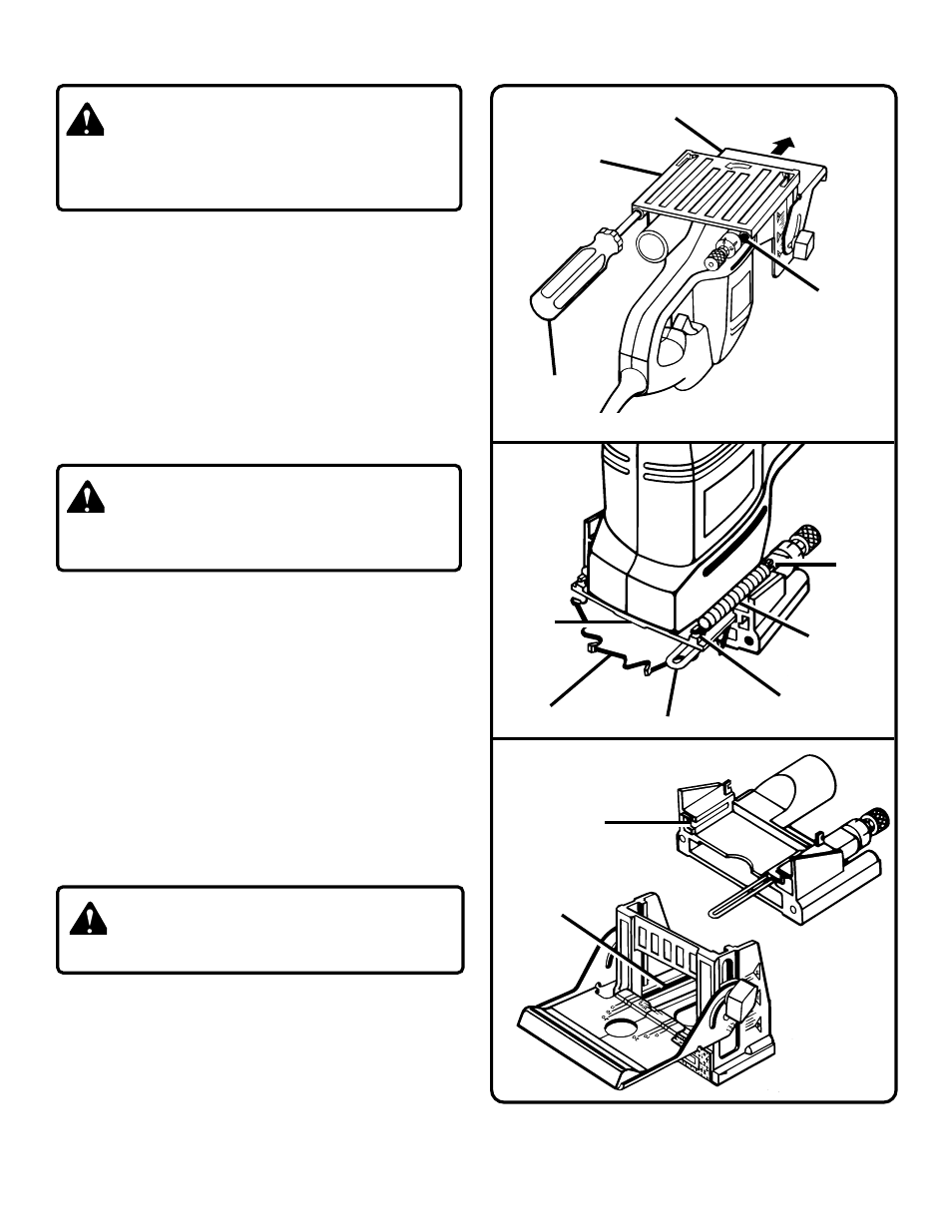
CLEANING BASE ASSEMBLY / DUST BAG
TUNNEL
See Figures 21-23.
After extended use, wood particles and resin may build up
inside the base assembly of your plate joiner and clog the
path for wood particles going into dust bag. Wood particles
packing up in this area, not only defeats the dustless feature
of your plate joiner, it also makes cutting biscuit slots more
difficult.
HOW TO CLEAN BASE ASSEMBLY
1. Unplug your plate joiner.
2. Remove dust bag.
3. Place your plate joiner upside down on a workbench as
shown in figure 21.
4. Using a screwdriver remove the two screws securing
front base assembly.
5. Pull adjustable fence in the direction shown by the arrow
in figure 21 and remove front base assembly.
6. Using a pair of needle nose pliers, stretch and release
springs from tabs on bearing plate.
See Figure 22.
7. Push adjustment rod away from bearing plate and remove
rear base assembly.
8. With front and rear base assemblies removed, place your
plate joiner upside down on a workbench and clean wood
particles and resin from blade, bearing plate and
surrounding areas.
9. Clean wood particles and resin from slots and surrounding
areas on front and rear base assemblies.
See Figure 23.
Apply a thin coat of general purpose grease in slots or on
bearing plate where base slides.
10. Replace rear base assembly. Position adjustment rod in
its proper place as shown in figure 22.
11. Secure rear base assembly in place with the two springs.
Hook one end of each spring in notch on each side of
base assembly. Using needle nose pliers, stretch each
spring and hook it over tabs on bearing plate.
WARNING:
When servicing, use only identical Ryobi replacement
parts. Use of any other part may create a hazard or
cause product damage.
WARNING:
Failure to unplug your plate joiner could result in accidental
starting causing possible serious personal injury.
CAUTION:
Be aware of cut hazard, carbide tips on blade are sharp.
12. Reassemble front base assembly.
13. Replace screws and tighten securely with a screwdriver.
14. Replace dust bag.
FRONT
BASE ASSEMBLY
SLOTS
Fig. 22
BEARING
PLATE
Fig. 21
ADJUSTMENT ROD
BLADE
ADJUSTABLE
FENCE
FRONT BASE
ASSEMBLY
SCREW
HOLE
SCREWDRIVER
SHOWN WITHOUT DUST BAG
TAB(S)
SPRING(S)
NOTCH
REAR BASE
ASSEMBLY SLOTS
TO
REMOVE