Router mounting, Caution, Warning – Ryobi 4950300 User Manual
Page 9
Page 9
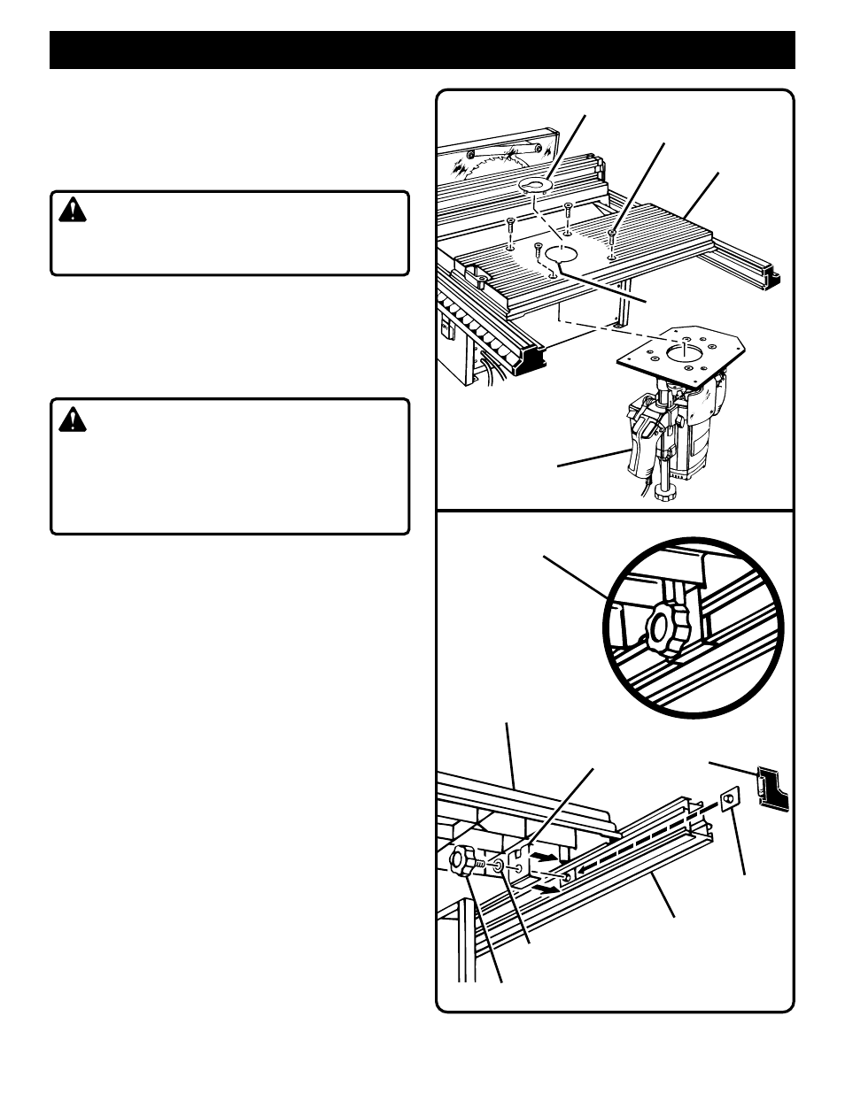
Fig.11
ROUTER MOUNTING
TABLE CLAMPING BRACKET
SHOWN COMPLETELY ASSEMBLED
ACCESSORY TABLE
TABLE
CLAMPING BRACKET
T-NUT
REAR RAIL
5/16 in. WASHER
KNOB BOLT
END PLUG
Fig.12
SLOT
THROAT PLATE
ACCESSORY TABLE
#1/4-20 SCREWS (PROVIDED)
ROUTER
WITH MOUNTING
PLATE ATTACHED
INSTALLING ROUTER BIT AND THROAT
PLATE:
■
Follow the instructions in the operator's manual of
your router for this procedure. Install router bit and
securely tighten in collet.
CAUTION:
Make sure the router bit will not strike the accessory
table or any metal surface.
■
Select the correct size throat plate for the size of the
router bit. Align the tab on the throat plate with the slot
in the accessory table and snap in place. Make sure
the throat plate is firmly seated below the table
surface. Recheck the router bit to make sure it will not
strike the throat plate.
WARNING:
The router throat plates are included to assure no
more than 1/4 in. (6.4 mm) clearance between the
cutter and the opening in the throat plate. Use correct
throat plate. Do not use a router bit smaller than 1/4
in. (6.4 mm) or larger than 2 in. (50 mm) in diameter.
TO ASSEMBLE TABLE CLAMPING BRACKET:
The lever on the accessory table will tighten the table
securely to the front rail. The weight of the router and
mounting plate may cause the accessory table to
loosen or have movement at the rear of the table. To
avoid this, install the table clamping bracket supplied
with this kit.
■
Remove end plug from rear rail as shown in
Figure 12.
■
Slide one of the T-nuts into the front channel of the
rear rail and under the accessory table.
■
The table clamping bracket fits in the bottom slot of
the rear rail. The slotted top of this bracket wraps
around the raised portion on the underside of the
accessory table clamping it tightly against the rear
rail.
■
Secure with a 5/16 in. washer and 5/16-18 x 3/4 in.
knob bolt.
■
Tighten knob bolt securely.