Router mounting, Warning – Ryobi 4950300 User Manual
Page 6
Page 6
ROUTER MOUNTING
Fig. 4
GUARD/DUST COVER WITH
PIVOT ASSEMBLY
KNOB NUT
FLATS ON
POST
POST
KNOB
BOLTS
5/16 in.
WASHERS
GUIDE FENCE
BRACKET
RIP FENCE
T-NUTS
CARRIAGE BOLT
(NOT SHOWN)
SPACER
Fig. 5
ROUTER
MOUNTING
SCREWS
ROUTER
MOUNTING
PLATE
ROUTER WITH 2–HOLE PATTERN
SUBBASE
ROUTER
BASE
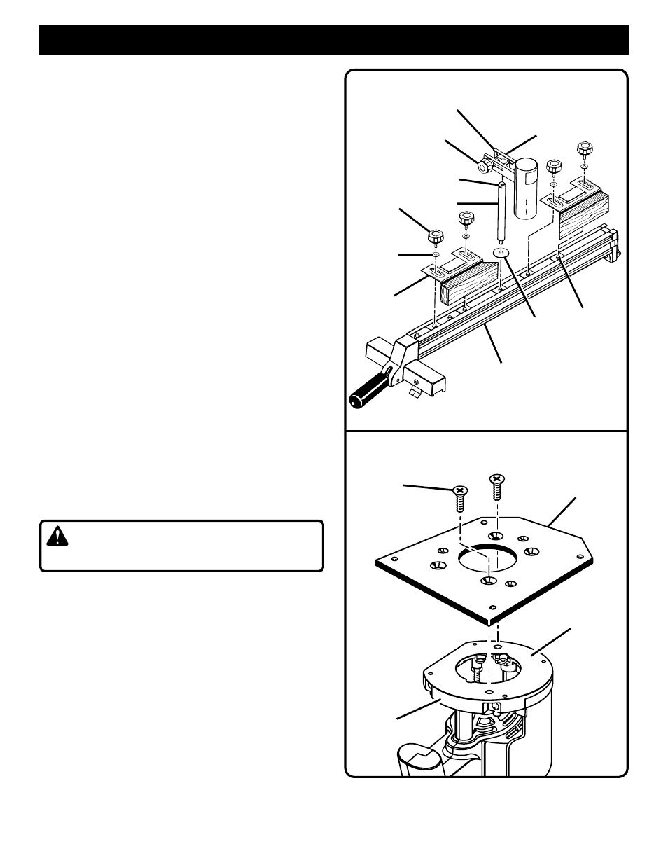
TO INSTALL GUIDE FENCE BRACKETS:
■
To install the guide fence brackets, align each bracket
with two of the T-nuts on top of the rip fence.
See
Figure 4.
Note: Use the front two T-nuts and the back two T-
nuts leaving the one in the middle empty.
■
Secure the guide fence brackets to the rip fence with
5/16 in. washers and the 5/16 in. x 1/2 in. knob bolts.
TO INSTALL POST, GUARD/DUST COVER
WITH PIVOT ASSEMBLY:
■
Place the spacer on the threaded end of the post and
thread the post into the remaining T-nut.
See Figure 4.
■
Tighten the post securely with an adjustable wrench
on the flats on the top of the post.
■
Place the guard/dust cover with pivot assembly on
the post.
See Figure 4.
■
The assembly will slide up and down on the post as
needed. Secure at the desired location by tightening
the knob nut attached to the carriage bolt.
TO ASSEMBLE ROUTERS WITH 2-HOLE
PATTERN TO ROUTER MOUNTING PLATE:
See Figures 5 and 6.
Note: For Ryobi routers, model numbers R175 and
RE175. Model R175 must also use #4830175 depth
control kit.
■
Unplug the router.
WARNING:
Unplug the router to avoid
possible injury.
■
The black plastic subbase is glued to the router
base. Do not remove. Make sure the router switch is
OFF and the router is not connected to a power
source.
■
Place the router upside down on a workbench and
align mounting holes of the mounting plate with the
two threaded holes in the router base.
■
The switch handle of the router should be facing the
squared end of the mounting plate.
See Figure 5.