Router mounting, Warning – Ryobi 4950300 User Manual
Page 8
Page 8
Fig. 9
Fig. 10
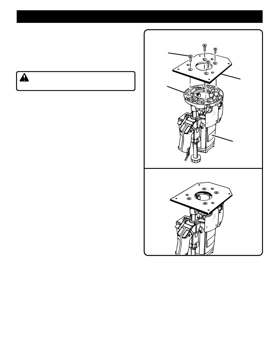
ROUTER MOUNTING
4–HOLE ROUTER WITH MOUNTING PLATE ATTACHED
ROUTER
MOUNTING
SCREWS
FRONT
OF ROUTER
ROUTER
MOUNTING
PLATE
ROUTER WITH 4–HOLE PATTERN
TO ASSEMBLE ROUTERS WITH 4-HOLE
PATTERN TO ROUTER MOUNTING PLATE:
See Figures 9 and 10.
Note: For Ryobi routers, model numbers RE600 and
RE601.
■
Unplug the router.
WARNING:
Unplug the router to avoid
possible injury.
■
Make sure the router switch is OFF and the router is
not connected to a power source.
■
Place the router upside down on a workbench and
remove the subbase screws and subbase from the
router.
■
Align mounting holes of the mounting plate with the
four threaded holes in the router base.
■
The switch handle of the router should be facing the
squared end of the mounting plate.
See Figure 9.
■
Secure the router mounting plate to the router using
four M8 flat head screws provided in the router
mounting kit.
■
Properly installed, the mounting plate will be securely
attached to the router.
See Figure 10.
■
Tighten screws securely.
TO ASSEMBLE MOUNTING PLATE WITH
ROUTER ATTACHED TO ACCESSORY TABLE:
■
Place the router and the mounting plate under the
accessory table.
See Figure 11.
■
Secure the mounting plate to accessory table using
the four #1/4-20 x 1/2 in. flat head screws provided.
Note: The accessory table can be removed from the
table saw to attach the router and mounting plate.
Follow instructions in the table saw operator's manual
for removing and reattaching the accessory table.
■
Tighten screws securely.
ROUTER
BASE