Petsafe Innotek Smart Dog® Rechargeable In-Ground Pet Fencing System User Manual
Page 8
Innotek, Inc. (800)-826-5527 www.innotek.net
the opposite side of the house. When at a distance from the
corner of the house equal to the containment field width less
one foot, do a hairpin turn and continue positioning the wire a
distance of the field width plus three feet away from itself.
Proceed around the back yard until you return to the opening
leading to the wall transmitter. This design will keep the back
entrances to the house free from corrective signals.
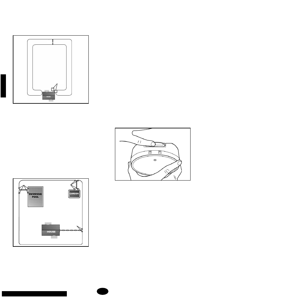
Your containment installation can be customized to protect
areas such as gardens, pools, and specific landscaping. To
accomplish this, encircle the protected area with containment
wire. Use twisted wire equal to the distance between the pro-
tected area and the containment perimeter. Use waterproof
splices to connect the twisted wire to the containment wire at
the perimeter and at the protected area. The containment
signal is cancelled where the twisted wire is located thus
allowing your dog to run around the garden or pool without
receiving stimulation. The containment signal around the pro-
tected area will keep your dog out just as the perimeter con-
tainment wire keeps him in.
Once you are satisfied with the layout of your containment
system, it is time to choose a proper location for the wall-
mount transmitter.
B. Installing the Wall-Mount Transmitter
1. Select a Location for the Wall-Mount Transmitter.
Select a location for the wall-mount transmitter that is within
five feet of a standard, grounded 110-volt household outlet
and will provide easy access to an exterior wall where the
containment wire can penetrate. When selecting a location,
keep in mind that you will need easy access to the transmit-
ter for recharging the receiver and where you will be able to
hear any alarms. Consider going through a windowsill or door
frame whenever possible. Mark the desired location with a
pencil.
The transmitter may be mounted on a hollow wall or directly
to a wall stud using the provided mounting hardware. The
wall-mount transmitter must be located in a dry, enclosed
area where the temperature range will be between 32ÞF and
110ÞF (0ÞC to 45ÞC). Preferable locations are the garage,
laundry room, office, or finished basements. These areas are
used frequently, so the system information generated by the
wall transmitter is likely to be checked more regularly. For
ease in monitoring this information, mount the transmitter at
least four feet from the floor.
2. Install the Mounting Plate.
Remove the mounting plate from the back of the transmitter
by lightly depressing the dot on the top tab (see illustration)
and sliding the transmitter housing down off the mounting
plate.
Making sure the mounting plate is level, use the mounting
plate as a template to transfer the position of the two mount-
ing holes onto the mounting location by tracing the holes with
a pencil.
Make sure there are no electrical wires or other objects direct-
ly behind the mounting-hole locations that might be damaged
when the mounting screws are installed.
For hollow wall installations, drill 1/4-inch diameter holes at
the marked locations and tap in the hollow wall fasteners with
a hammer. For installation of mounting screws directly into a
wall stud, drill 3/32-inch diameter pilot holes at the marked
locations.
8.
splices
splices
splices
Customized Layout
INSTALLATION
splice
6 ft.
Double Loop