Petsafe In-Ground Fence™ User Manual
Page 12
12 1-800-732-2677
1. Turn the power OFF to the outlet that the Surge Protector
and Fence Transmitter will be plugged into.
2. We recommend that, if possible, use the outlet center
screw that holds the cover plate in place to secure the
Surge Protector to the outlet. To do this, tape the top of
the cover plate to the wall, then remove the cover plate
center screw. Plug the Surge Protector into the lower outlet
and then secure the cover plate using the longer screw
included with the protector. The screw is for mechanical
attachment only and does not ground the protector.
Remove the tape and turn ON the power to the outlet.
3. Run the Boundary Wire through a window, under a door,
through a crawl space vent, or any other appropriate
available access. You can also drill a hole through your wall.
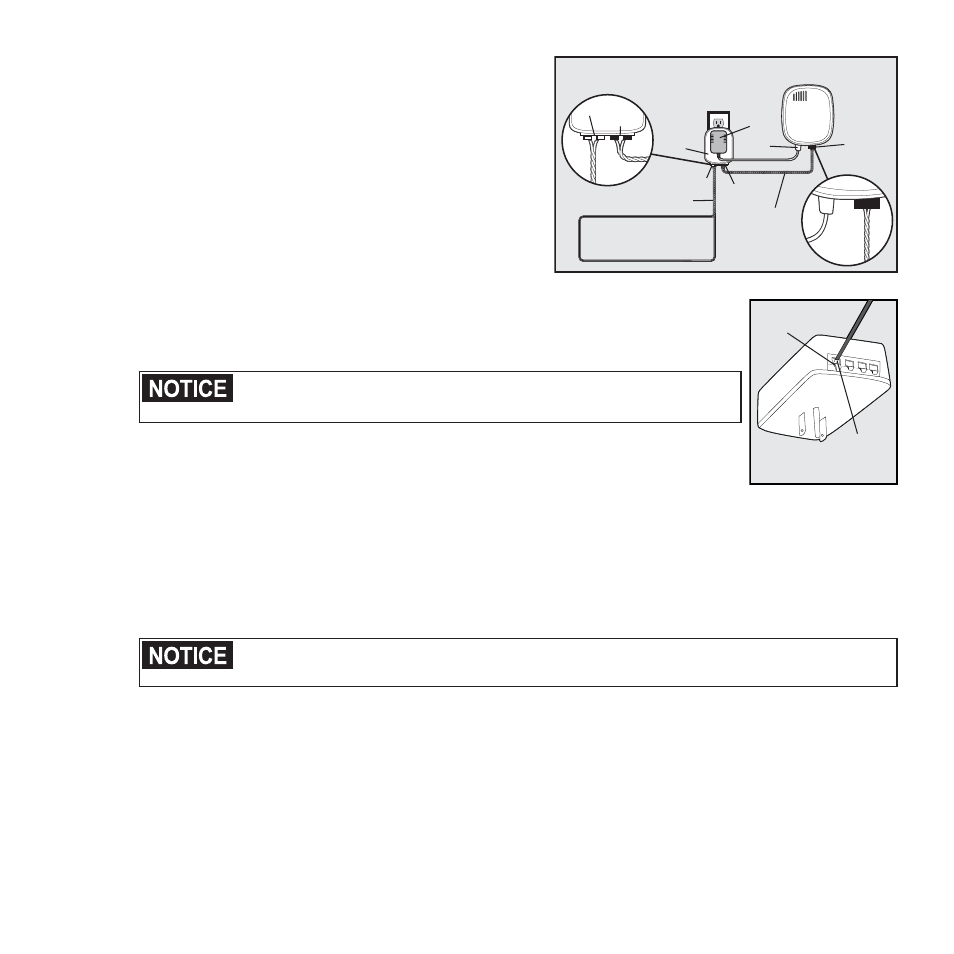
Fence Transmitter
Power
Adapter
Red Loop Tabs
Boundary Wires
(Twisted)
Boundary
Wire
Terminals
Transmitter
Wires
(Twisted)
Boundary Wire
Loop
Black
Transmitter
Tabs
LP-4100
Power
Jack
Transmitter
Loop
4A
4. Strip
3
⁄
8
inch of insulation from the ends of the Boundary Wire. Insert the stripped ends
into the 2 left red connector holes on the bottom of the Surge Protector labeled “Loop”
(4B). There should be 1 wire in each connector hole. Press the plastic tab, insert the
wires and release the tab. Make sure the wires do not touch each other at the terminals.
Verify that the boundary loop and transmitter wires connect to the
proper Surge Protector terminals. Reversed connections will result in an
increased risk of surge related damage.
5. Determine the length of wire needed to pass from the Surge Protector to the Fence
Transmitter. Measure and cut 2 lengths of wire, then strip
3
⁄
8
inch of insulation at both
ends. Twist the 2 lengths together, with at least 10-12 twists per foot, so the wires will
not send out a signal.
LOOP TRAN
SMITTER
Push Tab
Down
Insert bare end
of wire into
opened slot
and release tab
to lock.
4B
6. Insert the ends of the the twisted transmitter wires into the right 2 black connectors at the bottom of the Surge
Protector labeled “Transmitter”.
7. Press the red plastic tabs on the Fence Transmitter and insert the opposite ends of the twisted wire into the
Boundary Wire Terminals.
8. Turn the Boundary Width Control knob to 10. This will set the Boundary Width at the maximum width.
9. Plug in the transmitter power adapter to the outlet on the front of the Surge Protector.
10. The Power Light and Loop Indicator Lights should come on. If this does not happen, see the “Troubleshooting”
section.
For added protection, when unused for long periods of time or prior to thunderstorms, unplug from the
wall outlet and disconnect the loop boundary wires. This will prevent damage to the transmitter due to
surges.