2 physical description, Sm4m/sm16m storage module user guide, Figure 1-1 storage module and sc12 cable – Campbell Hausfeld SM4M User Manual
Page 8
SM4M/SM16M Storage Module User Guide
1-2
Power Requirements:
5 ±0.3V DC @ 100mA (max.)
Current drain:
Active, processing,
e.g. memory test:
3040mA (avg.)
Active, but waiting,
e.g. communications mode:
10mA (avg.)
Typical current during data
storage from a datalogger:
15mA (avg.)
Low Power Standby State:
less than 200
µ
A.
Peak current (flash erase):
60mA
Maintenance:
There are no user-serviceable parts inside the
Storage Module.
Logan, UT
SM4M
SN:
SO
LI
D
ST
AT
E
ST
OR
AG
E
MO
DU
LE
MADE IN USA
ST
ATUS
W
R
ITE
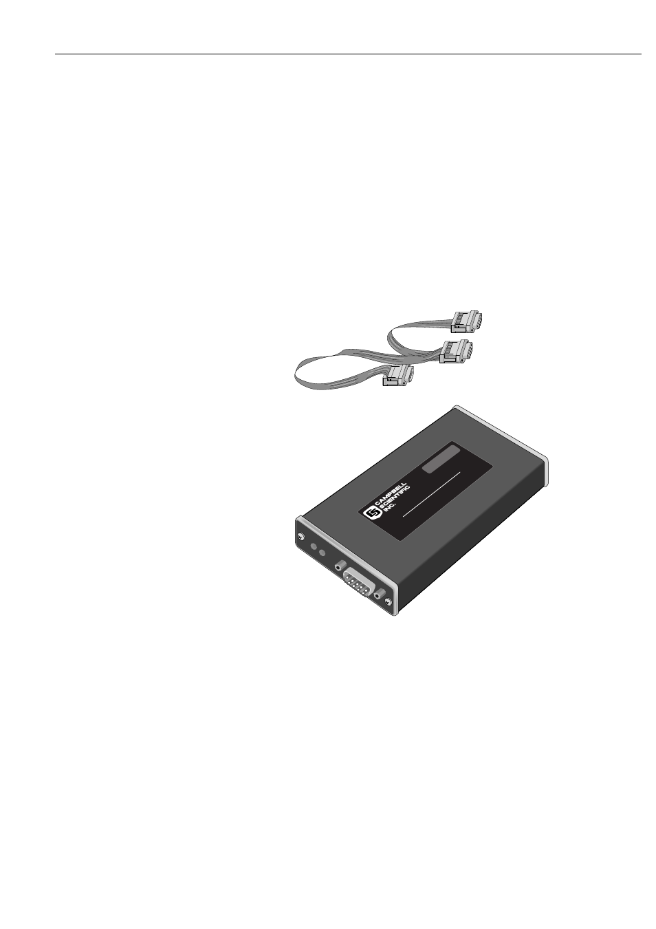
Figure 1-1 Storage Module and SC12 Cable
1.2 Physical Description
The Storage Module is housed in a sealed canister with a single, 9- pin
D-connector. The Storage Module is connected to a datalogger via the SC12
9-conductor ribbon cable.
There are two LEDs (light emitting diodes) adjacent to the connector. A red status
LED indicates the operational status of the module at power-up (see section 1.4)
and a green LED lights when data is being stored in the module.
The SM4M and SM16M are identical except for the amount of memory they
contain. The internal memory is split into 64kb blocks. There are 64 blocks of