Connecting units to form combinations – Nexen MBU-1125 937300 User Manual
Page 8
8
FORM NO. L-21087-C-1010
ALL MODELS AND MOTOR TO A REDUCER
1. Place the Key (Item 19) into the output shaft of the Modular
Unit and slide the output shaft of the Modular Unit and motor
into the reducer.
2. Rotate the Modular Unit and motor until the holes in the
Modular Unit are aligned with the holes in the reducer flange,
and the air inlet ports of the Modular Unit are facing down.
3. Using four Hex. Head Cap Screws, secure the Modular Unit
and motor to the reducer.
4. Alternately and evenly tighten the four Hex. Head Cap
Screws, making sure the Modular Unit and reducer faces
are flush with each other.
TABLE 1
MODELS 1125 AND 1375 TO A MOTOR
1. Remove the six Machine Screws (Item 25) that secure the
Friction Facing (Item 9) to the Disc Journal (Item 8) and save
the Machine Screws and Friction Facing as spare parts (See
Figure 5).
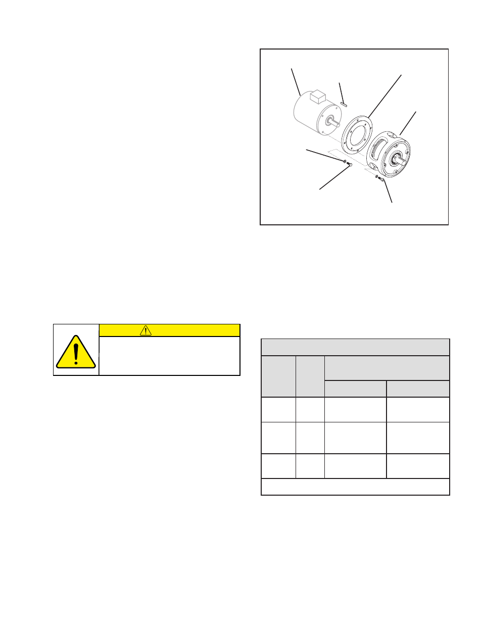
2. Place the Motor Adaptor Assembly (Product No. 937000)
on the mounting surface of the Modular Unit (See Figure
6).
3. Using the four Socket Head Cap Screws (Item 31), secure
Motor Adaptor Assembly to the Modular Unit (See Figure
6).
4. Alternately and evenly tighten the four Socket Head Cap
Screws (Item 31) to 50 ft-lb [69 Nm] torque (See Figure
6).
5. Place the Key (Item 19) into the motor shaft; then, slide the
motor shaft into the Modular Unit (See Figure 6).
6. Rotate the Modular Unit until the holes in the Modular Unit
are aligned with the tapped holes in the motor; then, using
the four Hex. Head Cap Screws (Item 33) and Lock Washers
(Item 24), secure the motor to the Modular Unit (See Figure
6).
Motor Adaptor
Assembly
Modular
Unit
Motor
Key
(Item 19)
Hex. Head
Cap Screw
(Item 33)
Socket Head
Cap Screw
(Item 31)
Lock
Washer
(Item 24)
FIGURE 6
CONNECTING UNITS TO FORM COMBINATIONS
(continued...)
(continued...)
CAUTION
When mounting sheaves or sprockets,
refer to Table 1 for overhung load data.
Exceeding the data in Table 1 will result
in premature failure to the Modular Unit.
7. Alternately and evenly tighten the four Hex. Head Cap
Screws to 20 ft-lb [27 Nm] torque.
A
T
A
D
D
A
O
L
G
N
U
H
R
E
V
O
L
E
D
O
M
M
P
R
t
o
li
P
m
o
r
f
]
m
m
4
.
5
2
[
''
1
d
a
o
L
*
e
c
a
F
5
2
1
1
5
7
3
1
U
B
M
0
0
2
1
0
0
8
1
.
s
b
L
636
.
s
b
L
4
4
5
.
s
b
L
0
0
7
.
s
b
L
0
1
6
U
O
M
0
0
2
1
0
0
8
1
.
s
b
L
6
3
6
.
s
b
L
4
4
5
.
s
b
L
0
0
7
.
s
b
L
0
1
6
U
I
M
0
0
2
1
0
0
8
1
.
s
b
L
5
5
6
.
s
b
L
0
7
5
.
s
b
L
5
5
6
.
s
b
L
0
7
5
.r
i
a
i
s
p
0
5
g
n
i
s
u
d
n
a
e
fi
l
e
g
a
r
e
v
a
.
s
r
h
0
0
0
,
0
1
n
o
d
e
s
a
B
*
- MBU-1375 937600 MBU-1375 937601 MOU-1125 937400 MOU-1375 937700 MDU-1375 937500 MDU-1125 937200 1375 Input Unit 937100 1125 Input Unit 937100 Modular 1375 936900 Modular-1375 937000 Modular 1125 936900 Modular-1125 937000 MDB-1125 935500 MDO-1125 935400 MDU-1125 935100 MDB-1375 936500 MDO-1375 936400