Disengagement torque setting, Caution, Cw ccw din 1816 positive stop – Nexen MTL2055 976889 User Manual
Page 6
FORM NO. L-21219-D-0610
6
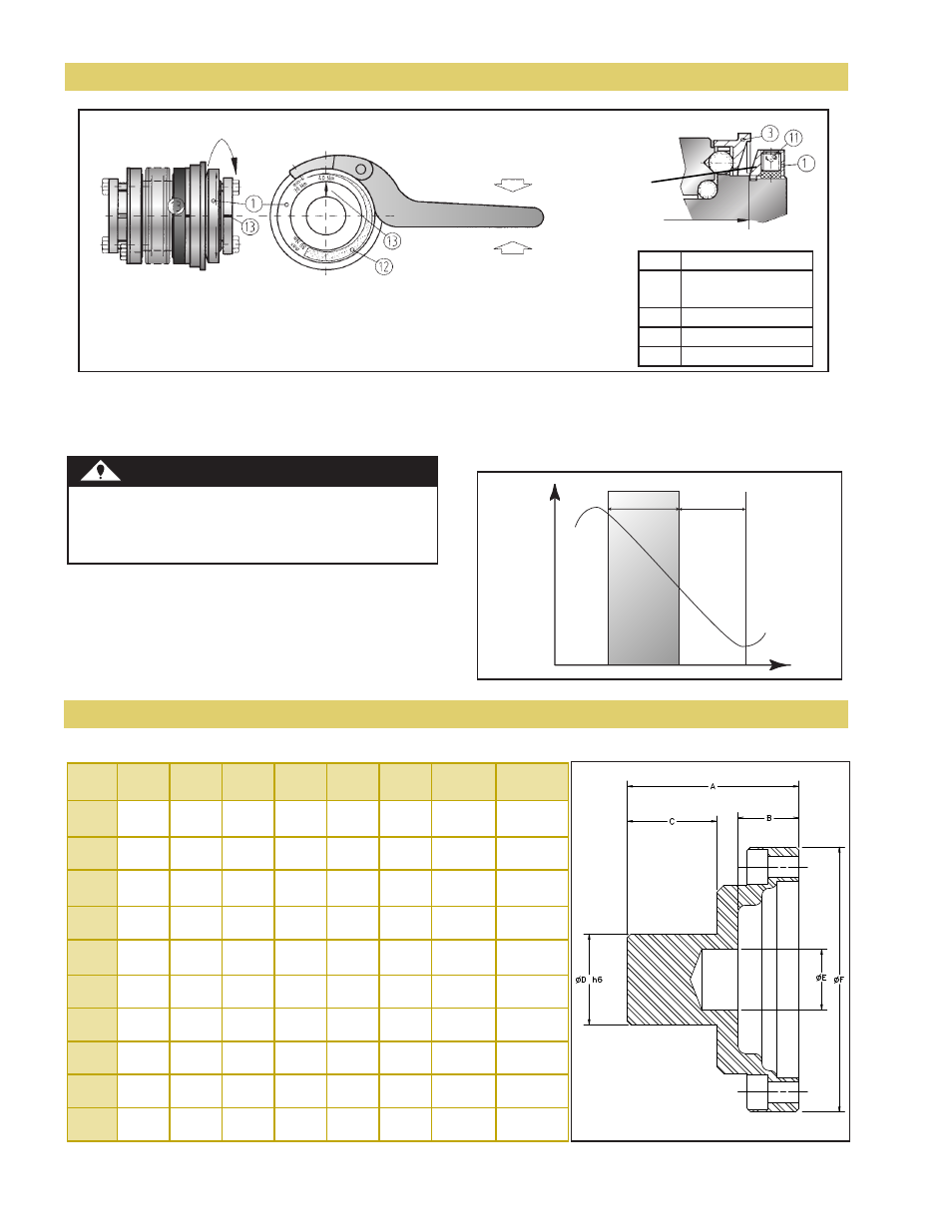
Disengagement Torque Setting
Nexen torque limiters are factory set to minimum disengagement torque within a specific range, which is marked
on the MTL. The adjustment range (min/max) is also marked on the adjustment ring. The customer can adjust the
disengagement torque as long as it falls into the range (12 )indicated on the adjustment ring.
CW
CCW
DIN 1816
Positive Stop
Spring has a
steeper angle
(not as flat).
Adjust nut flush
with hub end.
Flattens spring.
Adjustment stops
at shoulder.
CW Rotation Decreases Torque
CCW Rotation Increases Torque
Figure 4
1
Adjustment Nut
11
Fastening Screw /
Plastic cushion not shown
3
Steel Actuation Ring
12
Adjustment Range
13
Marking
CAUTION
Nexen torque limiters incorporate disc springs that
exhibit a special spring characteristic. It is important
to stay in the max-min range of the MTL.
To adjust the disengagement torque, loosen the
locking screws (11) and rotate the adjustment ring
using the spanner wrench to the desired new setting.
Tighten set screws and test the torque limiter. Note:
The set screws are used with plastic inserts to
prevent hub thread damage.
Actuation Path
Adjustment Range
Spring Path
S
pr
in
g
Fo
rc
e
T min
KN
T max
CN
Figure 5
Coupling Adapters - For Inch-Bored, Elastomer (Spider) Couplings
Figure 6
Series
A
B
C
D
E
F
Fastener Tightening
Torque
15
37
[1.465]
20
[0.787]
13
[0.520]
19.05
[0.750]
12
[0.480]
56
[2.205]
M4
4 Nm
[3 ft/lbs]
30
44
[1.740]
22
[0.866]
18
[0.697]
19.05
[0.750]
12
[0.480]
64
[2.520]
M5
4 Nm
[3 ft/lbs]
60
48
[1.886]
25
[0.984]
17
[0.665]
25.40
[1.000]
17
[0.669]
74
[2.913]
M5
7 Nm
[5 ft/lbs]
150
52
[2.063]
25
[0.984]
20
[0.803]
25.40
[1.000]
17
[0.669]
90
[3.543]
M6
12 Nm
[9 ft/lbs]
200
68
[2.677]
40
[1.575]
22
[0.846]
38.10
[1.500]
17
[0.669]
98
[3.858]
M6
14 Nm
[10 ft/lbs]
300
73
[2.854]
40
[1.575]
25
[0.984]
38.10
[1.500]
17
[0.669]
114
[4.488]
M8
18 Nm
[13 ft/lbs]
500
82
[3.209]
40
[1.575]
33
[1.299]
38.10
[1.500]
26
[1.024]
128
[5.039]
M8
25 Nm
[18 ft/lbs]
800
92
[3.630]
50
[1.969]
31
[1.228]
50.80
[2.000]
31
[1.221]
140
[5.512]
M10
36 Nm
[27 ft/lbs]
1500
99
[3.894]
50
[1.969]
39
[1.532]
50.80
[2.000]
31
[1.221]
170
[6.693]
M12
70 Nm
[52 ft/lbs]
2500
143
[5.638]
80
[3.150]
51
[2.016]
76.20
[3.000]
51
[2.005]
240
[9.449]
M16
180 Nm
[132 ft/lbs]
Table 2
- MTL1500 976888 MTL800 976887 MTL500 976886 MTL300 976885 MTL200 976884 MTL150 976883 MTL60 976882 MTL30 976881 MTL15 976880 MTL800-PCC-SP-75MM-400/650 976575-400 MTL300-PCC-SP-56MM-100/200 976175-100 MTL30-PMT-FD-20MM-8/20 975240-008 MTL150-PCC-MP-38/25-45/150 975680-080 MTL30-PCC-SP-25MM-10/25 975375-010 MTL15-PCC-SP-22MM-8/20 975175-008 MTL1500-2TC-SP-70MM-650/850 976700-600 MTL500-2TC-SP-60MM-80/200 976300-080 MTL800-2TC-SP-60MM-400/650 976500-400 MTL300-2TC-SP-56MM-100/200 976100-100 MTL500-2TC-FD-45MM-250/500 976301-500 MTL200-2TC-SP-44MM-30/90 975900-030 MTL200-2TC-SP-40MM-1.500-60/160 975901-060 MTL150-2TC-SP-37MM-20/70 975700-020 MTL60-2TC-SP-29MM-10/30 975500-010 MTL60-2TC-FD-25MM-18MM-25/80-94MM 975511-050 MTL60-2TC-FD-25MM-18MM-25/80 975510-050 MTL30-2TC-SP-23MM-10/25 975300-010 MTL15-2TC-SP-22MM-5/10 975100-005 MTL15-PMT-SP-20MM-5/15 975007-010 MTL2500-2TC-SP-100MM-1500/2000 976900-1500 MTL500-2TC-SP-1.50-1.50-200/350 976302-283 MTL150-2TC-SP-1.250-45/150 975702-045 MTL150-2TC-SP-1.250-20/70 975701-035 MTL300-2TC-SP-1.250-150/240 976101-168 MTL150-2TC-SP-1.000-45/150 975704-058 MTL1500-2CC-SP-80MM-650/800 976760-650 MTL800-2CC-SP-75MM-400/650 976560-400 MTL500-2CC-SP-60MM-80/200 976360-080 MTL300-2CC-SP-60MM-100/200 976160-100 MTL200-2CC-SP-45MM-30/90 975960-030 MTL30-2CC-SP-30MM-10/25 975360-010 MTL15-2CC-SP-26MM-5/10 975160-005 MTL30-2CC-MP-20MM-20/40 975362-040 MTL300-2CC-FD-2.000-2.250-160/300 976170-186 MTL15-PMT-SP-20MM-35/70,38T,8MM HTD,SPCL 975013-050 MTL30-2CC-MP-0.750-10/25 975361-023 MTL15-2CC-FD-0.625-7/15 975161-012 MTL800-2CC-FD-1.937-450/800 976570-768 MTL200-2CC-SP-1.00-1.00-60/160 975961-060 MTL150-2CC-SP-1.000-45/150 975703-085 MTL2500-PMT-MP-75MM-1500/2000 976820-1500 MTL2500-PMT-SP-75MM-1500/2000 976800-1500 MTL2500-PMT-FD-75MM-1400/2200 976840-1400 MTL1500-PMT-MP-70MM-1000/1800 976622-1000 MTL1500-PMT-SP-70MM-1000/1800 976602-1000 MTL1500-PMT-MP-60MM-700/1200 976621-700 MTL1500-PMT-SP-60MM-700/1200 976601-700 MTL800-PMT-MP-60MM-650/950 976422-650 MTL800-PMT-SP-60MM-650/950 976402-650 MTL15-PMT-SP-20MM-35/70 975012-050 MTL1500-PMT-FD-60MM-1250/1500 976641-1250 MTL500-PMT-SP-56MM-320/650 976204-325 MTL500-PMT-SP-56MM-200/350 976203-200 MTL800-PMT-MP-55MM-500/800 976421-500 MTL800-PMT-SP-55MM-500/800 976401-500 MTL800-PMT-FD-55MM-450/850 976441-450 MTL800-PMT-MP-50MM-400/650 976420-400 MTL800-PMT-SP-50MM-400/650 976400-400 MTL500-PMT-MP-50MM-320/650 976222-325 MTL500-PMT-SP-50MM-320/650 976202-325 MTL500-PMT-FD-50MM-250/500 976242-250 MTL300-PMT-MP-50MM-220/440 976022-220 MTL300-PMT-SP-50MM-220/440 976002-220 MTL800-PMT-FD-50MM-200/400 976440-200 MTL15-PMT-SP-20MM-12/25,38T,8MM HTD,SPCL 975004-025 MTL1500-PMT-MP-48MM-600/800 976620-600 MTL1500-PMT-SP-48MM-600/800 976600-600 MTL500-PMT-MP-48MM-200/350 976221-200 MTL500-PMT-SP-48MM-200/350 976201-200 MTL1500-PMT-FD-48MM-1000/1250 976640-1000 MTL500-PMT-FD-48MM-100/300 976241-100 MTL200-PMT-MP-44MM-140/280 975822-140 MTL200-PMT-SP-44MM-140/280 975802-140 MTL500-PMT-MP-40MM-80/200 976220-080 MTL500-PMT-SP-40MM-80/200 976200-080 MTL500-PMT-FD-40MM-50/150 976240-050 MTL200-PMT-SP-40MM-30/90 975805-030 MTL30-PMT-MP-20MM-10/30 975220-010 MTL300-PMT-SP-38MM-220/440-440 976004-440 MTL150-PMT-SP-35MM-80/225-225 975607-225 MTL300-PMT-MP-35MM-150/240 976024-158 MTL200-PMT-MP-32MM-60/160 975821-060 MTL200-PMT-SP-32MM-60/160 975801-060 MTL300-PMT-MP-32MM-220/440 976025-385 MTL300-PMT-FD-32MM-160/300 976043-160 MTL300-PMT-MP-32MM-150/240 976021-150 MTL300-PMT-SP-32MM-150/240 976001-150 MTL200-PMT-FD-32MM-130/200 975841-130 MTL200-PMT-FD-30MM-80/140 975840-080 MTL150-PMT-SP-30MM-45/150 975605-045 MTL30-PMT-SP-20MM-10/30 975200-010 MTL200-PMT-MP-30MM-30/90 975820-030 MTL200-PMT-SP-30MM-30/90 975800-030 MTL300-PMT-SP-30MM-100/200 976003-100 MTL150-PMT-SP-29MM-80/225 975606-080 MTL60-PMT-SP-29MM-50/115 975406-050 MTL60-PMT-SP-29MM-10/30 975404-010 MTL150-PMT-MP-28MM-80/225 975622-080 MTL150-PMT-SP-28MM-80/225 975602-080 MTL150-PMT-FD-28MM-80/150 975642-080 MTL150-PMT-SP-25MM-80/225 975603-150 MTL300-PMT-FD-2.12-160/300-200 976042-200 MTL150-PMT-MP-25MM-45/150 975621-045 MTL150-PMT-SP-25MM-45/150 975601-101 MTL150-PMT-SP-25MM-45/150 975601-045 MTL150-PMT-FD-25MM-40/80 975641-040 MTL60-PMT-FD-25MM-30/60 975442-030 MTL60-PMT-SP-25MM-25/80 975403-076 MTL60-PMT-SP-25MM-25/80 975403-040 MTL60-PMT-SP-25MM-25/80 975403-030 MTL300-PMT-FD-25MM-120/180 976040-120 MTL300-PMT-MP-25MM-100/200 976020-100 MTL300-PMT-SP-25MM-100/200 976000-100 MTL30-PMT-FD-0.750-8/20-SP 975242-008 MTL60-PMT-SP-25MM-10/30 975407-014 MTL60-PMT-MP-24MM-25/80 975421-025 MTL60-PMT-SP-24MM-25/80 975401-025 MTL60-PMT-FD-24MM-20/40 975441-020 MTL60-PMT-MP-23MM-10/30 975426-010 MTL150-PMT-SP-22MM-80/225 975604-080 MTL30-PMT-MP-22MM-50/100 975272-074 MTL30-PMT-MP-22MM-20/60 975221-039 MTL30-PMT-MP-22MM-20/60 975221-020 MTL30-PMT-SP-22MM-20/60 975201-020 MTL30-PMT-SP-0.750-50/100 975205-070 MTL30-PMT-FD-22MM-16/30 975241-016 MTL60-PMT-MP-22MM-10/30 975420-010 MTL30-PMT-MP-22MM-10/30 975222-010 MTL60-PMT-FD-22MM-10/30 975440-010 MTL60-PMT-SP-22MM-10/30-10 975400-010 MTL15-PMT-MP-0.750-5/15-45 DEGREE DISENGAGEMENT 975022-005 MTL15-PMT-SP-0.750-5/15-SS 975011-005 MTL15-PMT-SP-0.750-5/15 975002-005 MTL15-PMT-SP-0.750-35/70 975010-060 MTL30-PMT-SP-0.750-20/60 975202-033 MTL15-PMT-SP-0.750-20/40 975009-040 MTL30-PMT-FD-0.750-16/30 975243-016 MTL15-PMT-SP-0.750-12/25 975003-012 MTL60-PMT-MP-0.750-10/30-45 DEGREE DISENGAGEMENT 975424-010 MTL60-PMT-SP-0.750-10/30 975405-010 MTL30-PMT-SP-0.750-10/30 975207-010 MTL150-PMT-MP-19MM-20/70 975620-020 MTL150-PMT-SP-19MM-20/70 975600-020 MTL150-PMT-FD-19MM-20/60 975640-020 MTL15-PMT-MP-19MM-12/25 975021-012 MTL15-PMT-SP-19MM-12/25 975001-012 MTL15-PMT-FD-16MM-7/15 975040-007 MTL15-PMT-MP-16MM-5/15 975020-005 MTL15-PMT-SP-16MM-5/15 975000-005 MTL30-PMT-SP-16MM-20/60 975203-033 MTL30-PMT-SP-16MM-10/25 975204-010 MTL15-PMT-MP-0.625-5/15 975024-005 MTL15-PMT-SP-0.625-5/15 975006-005 MTL30-PMT-SP-0.625-20/60 975206-033 MTL15-PMT-SP-0.625-20/40 975008-040 MTL15-PMT-SP-0.500-5/15 975005-005 MTL15-PMT-MP-12MM-5/15 975023-005 MTL2501-PMT-MP-100MM-2300/2800 976822-2300 MTL2501-PMT-SP-100MM-2300/2800 976802-2300 MTL2500-PMT-MP-100MM-2000/2500 976821-2000 MTL2500-PMT-SP-100MM-2000/2500 976801-2000 MTL2500-PMT-FD-100MM-1800/2700 976841-1800 MTL800-PMT-MP-1.938-650/950 976423-650 MTL300-PMT-MP-1.938-100/200 976023-100 MTL200-PMT-SP-1.750-60/160 975806-136 MTL200-PMT-FD-1.500-80/140-SP 975842-090 MTL200-PMT-SP-1.500-60/160 975803-060 MTL200-PMT-SP-1.500-140/280 975804-140 MTL150-PMT-SP-1.437-45/150 975644-060 MTL150-PMT-FD-1.437-40/80 975643-060 MTL500-PMT-SP-1.250-80/200 976206-136 MTL500-PMT-SP-1.250-200/350 976205-280 MTL60-PMT-SP-1.125-50/115 975408-090 MTL60-PMT-MP-1.00-50/115 975423-050 MTL60-PMT-MP-1.000-25/80 975422-025 MTL60-PMT-SP-1.000-25/80 975402-025 MTL60-PMT-MP-1.000-10/30-45 DEGREE DISENGAGEMENT 975425-010 MTL60-PMT-MP-1.000-10/30 975427-020 MTL15-PMT-FD-0.875-7/15 975041-007 MTL2500-PMK-MP-2.938-2300/2800 976872-2300 MTL2500-PMK-SP-2.938-2300/2800 976852-2300 MTL2500-PMK-MP-2.938-2000/2500 976871-2000 MTL2500-PMK-SP-2.750-2000/2500 976851-2000 MTL2500-PMK-FD-2.750-1800/2700 976891-1800 MTL2500-PMK-MP-2.750-1500/2000 976870-1500 MTL2500-PMK-SP-2.500-1500/2000 976850-1500 MTL2500-PMK-FD-2.500-1400/2200 976890-1400 MTL1500-PMK-MP-2.437-1000/1800 976672-1000 MTL1500-PMK-SP-2.437-1000/1800 976652-1000 MTL500-PMK-SP-2.250-200/350 976253-200 MTL1500-PMK-MP-2.188-700/1200 976671-700 MTL1500-PMK-SP-2.188-700/1200 976651-700 MTL800-PMK-MP-2.188-500/800 976473-670 MTL1500-PMK-FD-2.188-1250/1500 976691-1250 MTL800-PMK-MP-2.000-650/950 976472-650 MTL800-PMK-SP-2.000-650/950 976452-650 MTL30-PMK-FD-0.750-8/20 975292-011 MTL60-PMK-FD-0.750-30/60 975493-030 MTL60-PMK-MP-0.750-25/80 975471-025 MTL60-PMK-SP-0.750-25/80 975451-025 MTL30-PMK-MP-0.750-20/60 975271-020 MTL30-PMK-SP-0.750-20/60 975251-020 MTL60-PMK-FD-0.750-20/40 975491-020 MTL15-PMK-SP-0.750-20/40 975053-023 MTL30-PMK-FD-0.750-16/30 975291-016 MTL60-PMK-MP-0.750-10/30 975473-017 MTL60-PMK-SP-0.750-10/30 975457-017 MTL30-PMK-FD-0.625-8/20 975290-008 MTL30-PMK-MP-0.625-5/20 975270-010 MTL15-PMK-SP-0.625-5/15 975052-005 MTL15-PMK-SP-0.625-20/40 975054-030 MTL15-PMK-MP-0.625-12/25 975071-018 MTL15-PMK-MP-0.625-12/25 975071-012 MTL15-PMK-SP-0.625-12/25 975051-012 MTL60-PMK-FD-0.625-10/30 975490-010 MTL30-PMK-SP-0.625-10/30-20-SS 975252-020 MTL60-PMK-MP-0.625-10/30 975470-010 MTL30-PMK-SP-0.625-10/30 975250-010 MTL60-PMK-SP-0.625-10/30 975450-010 MTL60-PMK-SP-0.625-25/80 975453-076 MTL30-PMK-SP-14MM-5/20 975254-007 MTL15-PMK-FD-0.500-7/15 975091-007 MTL15-PMK-FD-0.500-7/15 975090-007 MTL15-PMK-MP-0.500-5/15 975070-005 MTL15-PMK-SP-0.500-5/15 975050-005 MTL500-PMK-MP-1.938-320/650 976273-532 MTL300-PMK-SP-1.938-150/240 976053-150 MTL1500-PMK-FD-1.938-1250/1500 976692-1250 MTL800-PMK-MP-1.875-500/800 976471-500 MTL800-PMK-SP-1.875-500/800 976451-500 MTL800-PMK-FD-1.875-450/850 976491-450 MTL1500-PMK-MP-1.750-600/800 976670-600 MTL1500-PMK-SP-1.750-600/800 976650-600 MTL500-PMK-MP-1.750-320/650 976272-325 MTL500-PMK-SP-1.750-320/650 976252-325 MTL500-PMK-FD-1.750-250/500 976292-250 MTL1500-PMK-FD-1.750-1000/1250 976690-1000 MTL800-PMK-MP-1.625-400/650 976470-400 MTL800-PMK-SP-1.625-400/650 976450-400 MTL800-PMK-FD-1.625-200/400 976490-200 MTL150-PMK-SP-1.500-80/225 975659-080 MTL150-PMK-SP-1.500-80/225 975653-110 MTL300-PMK-MP-1.500-220/440 976072-220 MTL300-PMK-SP-1.500-220/440 976052-220 MTL150-PMK-SP-1.438-80/225 975658-107 MTL1500-PMK-MP-1.438-700/1200-30 DISENGAGEMENT DEGREE 976673-1000 MTL150-PMK-SP-1.375-20/70 975660-048 MTL150-PMK-SP-1.250-80/225 975657-110 MTL200-PMK-SP-1.250-60/160 975854-104 MTL150-PMK-SP-1.250-45/150 975654-068 MTL300-PMK-MP-1.250-220/440 976054-390 MTL300-PMK-SP-1.250-220/440 976055-390 MTL500-PMK-MP-1.250-200/350 976271-200 MTL500-PMK-SP-1.250-200/350 976251-200 MTL150-PMK-SP-1.250-20/70 975655-050 MTL200-PMK-MP-1.250-140/280 975872-140 MTL200-PMK-SP-1.250-140/280 975852-140 MTL500-PMK-FD-1.250-100/300 976291-100 MTL60-PMK-SP-1.188-10/30-19 975452-019 MTL150-PMK-MP-1.125-80/225 975672-080 MTL150-PMK-SP-1.125-80/225 975652-080 MTL150-PMK-FD-1.125-80/150 975692-080 MTL60-PMK-MP-1.125-50/115 975472-113 MTL60-PMK-SP-1.125-25/80 975458-047 MTL300-PMK-MP-1.125-150/240 976071-150 MTL300-PMK-SP-1.125-150/240 976051-150 MTL150-PMK-SP-1.000-80/225 975656-204 MTL150-PMK-SP-1.000-80/225 975656-110 MTL500-PMK-MP-1.000-80/200 976270-080 MTL500-PMK-SP-1.000-80/200 976250-080 MTL200-PMK-MP-1.000-60/160 975871-060 MTL200-PMK-SP-1.000-60/160 975851-060 MTL500-PMK-FD-1.000-50/150 976290-050 MTL150-PMK-MP-1.000-45/150 975671-045 MTL150-PMK-SP-1.000-45/150 975651-045 MTL150-PMK-FD-1.000-40/80 975691-040 MTL60-PMK-SP-1.000-25/80 975456-025 MTL200-PMK-SP-1.000-140/280 975853-250 MTL200-PMK-FD-1.000-130/200 975891-130 MTL300-PMK-FD-1.000-120/180 976090-120 MTL300-PMK-MP-1.000-100/200 976070-100 MTL300-PMK-SP-1.000-100/200 976050-100 MTL60-PMK-SP-1.000-10/30 975454-010 MTL200-PMK-FD-0.875-80/140 975890-080 MTL200-PMK-MP-0.875-30/90 975870-030 MTL200-PMK-SP-0.875-30/90 975850-030 MTL60-PMK-FD-0.875-30/60 975492-030 MTL60-PMK-SP-0.875-25/80 975455-061 MTL150-PMK-MP-0.875-20/70 975670-020 MTL150-PMK-SP-0.875-20/70 975650-020 MTL150-PMK-FD-0.875-20/60 975690-020 MTL30-PMK-SP-0.8125-20/60-SS 975253-035 MTL800-ECC-SP-75MM-400/650 976530-400 MTL300-ECC-SP-56MM-100/200 976130-100 MTL150-ECC-SP-38MM-20/70 975730-020 MTL300-ECC-SP-32MM-20MM-150/240 976131-225