Nexen PRD750 966901 User Manual
Page 9
9
FORM NO. L-21265-B-0312
To ensure optimal meshing of the roller pins with the
gear teeth, the shaft must be preloaded to 0.010 -
0.015 mm [0.0004 - 0.0006 in] beyond full roller/
tooth root engagement.
NOTE: Do not apply excessive preload. Preloading
beyond 0.015 mm [0.0006 in] will decrease
product life, increase noise, and cause
vibration. When the PRD system is
properly preloaded, there will be no
tangential play between the gear teeth
and the pinion rollers if the pinion is not
allowed to turn and the rotating assembly
forced back and forth in the direction of
rotation.
Preloading Procedure
Note: Be careful when engaging the pinion and
servo assembly to the gear to avoid damaging
the gear teeth or pinion rollers.
1. With a dial indicator mounted on the movable
carriage, measure off the tooth peaks. Move
the carriage down the run taking frequent
measurements to locate the high spot in the run.
This is where the pinion preloading should be
done to prevent excessive preload from occurring
elsewhere in the run.
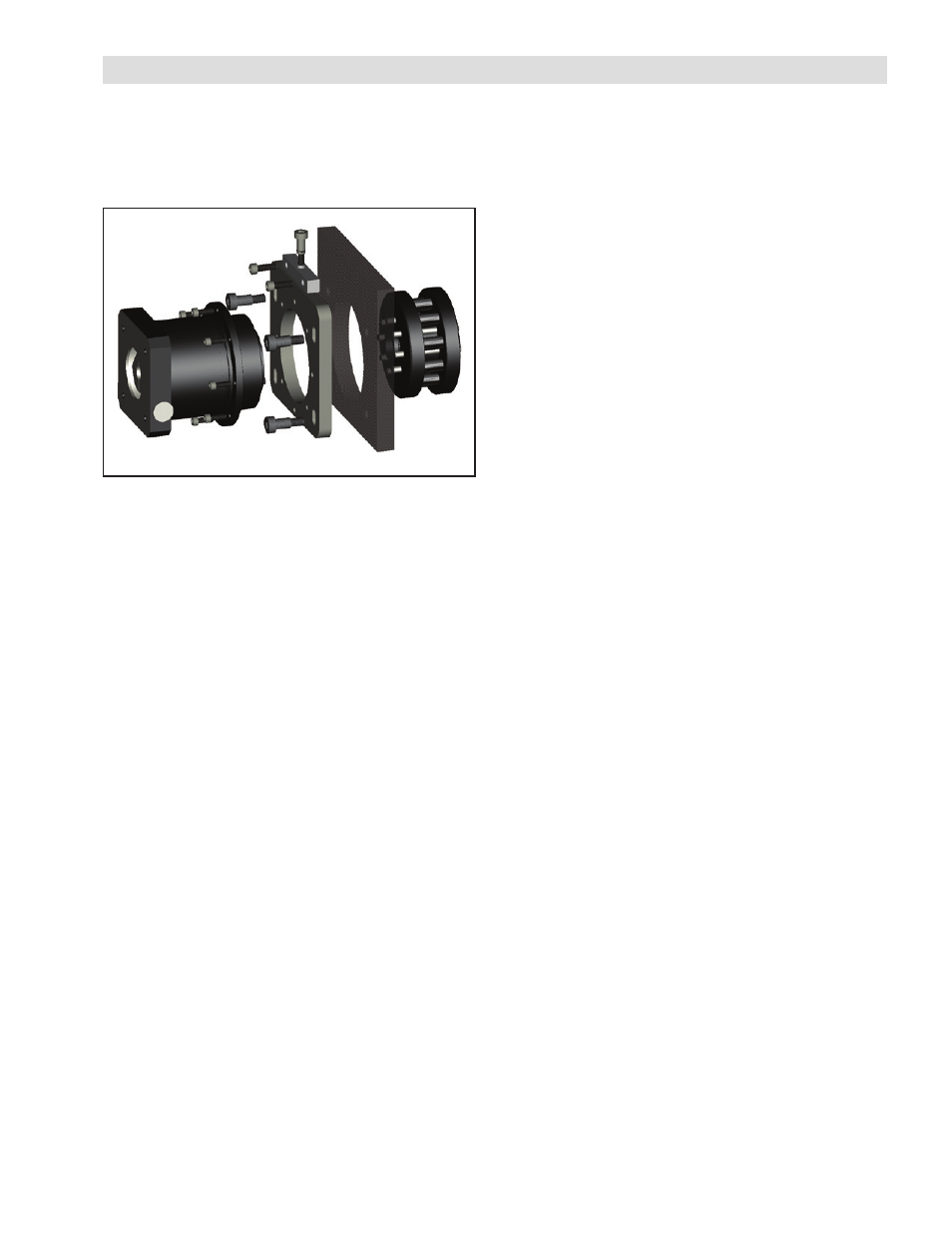
PRELOAD
The PRD is delivered with proper preload from the
factory. If adjusting the preload is required, a tool
can be purchased from Nexen to aid in this process.
The Nexen preloader is configured as shown below
in Figure 4.
Figure 4
2. Apply serviceable thread locking compound to the
pinion preloader slider bolts and install the servo
and preload mechanism. Ensure the preload
related bolts are just loose enough to allow the
pinion to be pulled away from the gear teeth. For
the Nexen Preloader System, this is approximately
0.2 - 0.3 Nm [2 - 3 in-lbs].
3. Verify that the pinion rotational axis is as parallel as
possible to the gear’s rotational axis, and the gear
is centered between the pinion bearing flanges.
4. Rotate the preload adjustment screw clockwise
to separate the pinion from the gear. This will
ensure that clearance is initially present. Then
seat the pinion into contact by turning the preload
adjustment screw counterclockwise until a slight
resistance is felt and then back the screw off 1/8
of a turn. This step is critical to prepare for preload
settings.
5. Place a magnetic base dial indicator on the same
part of the machine as the motor and reducer, and
locate its probe on the OD of the pinion flange
such that it measures in the direction of preload
travel.
6. Apply the preload of 0.010 - 0.015 mm [0.0004
- 0.0006 in] with the preload application screw(s)
and then tighten the M8 x 1.25 preload lockdown
bolts to their recommended torque of 40 Nm (350
in-lbs). Typically the preload will change slightly
when the preloader lockdown bolts are tightened.
If tightening the preload bolts causes the amount
of preload to fall outside of specifications,
record how much it changed when tightening
the preloader lock down bolts then loosen the
preloading system and repeat the preloading
procedure but adjust the initial preload (more
or less) by the recorded preload deviation. This
procedure will ensure that when the preloader
lockdown bolts are tightened the amount of
preload should fall within specifications.
7. With the pinion preloaded to specifications
manually rotate the gear by hand (if possible)
checking for smoothness and uniformity of
resistance. If manually applied motion is not
possible, use the servo motor to rotate the gear,
with just enough torque output to move it while
looking and listening for resistance to motion.