Nexen PRD750 966901 User Manual
Page 7
7
FORM NO. L-21265-B-0312
INSTALLATION INSTRUCTIONS
Ring Drive Mounting
Nexen recommends removing the guards before
installation. The mounting holes are accessible thru the
guard, but removing the guard will make the process
easier.
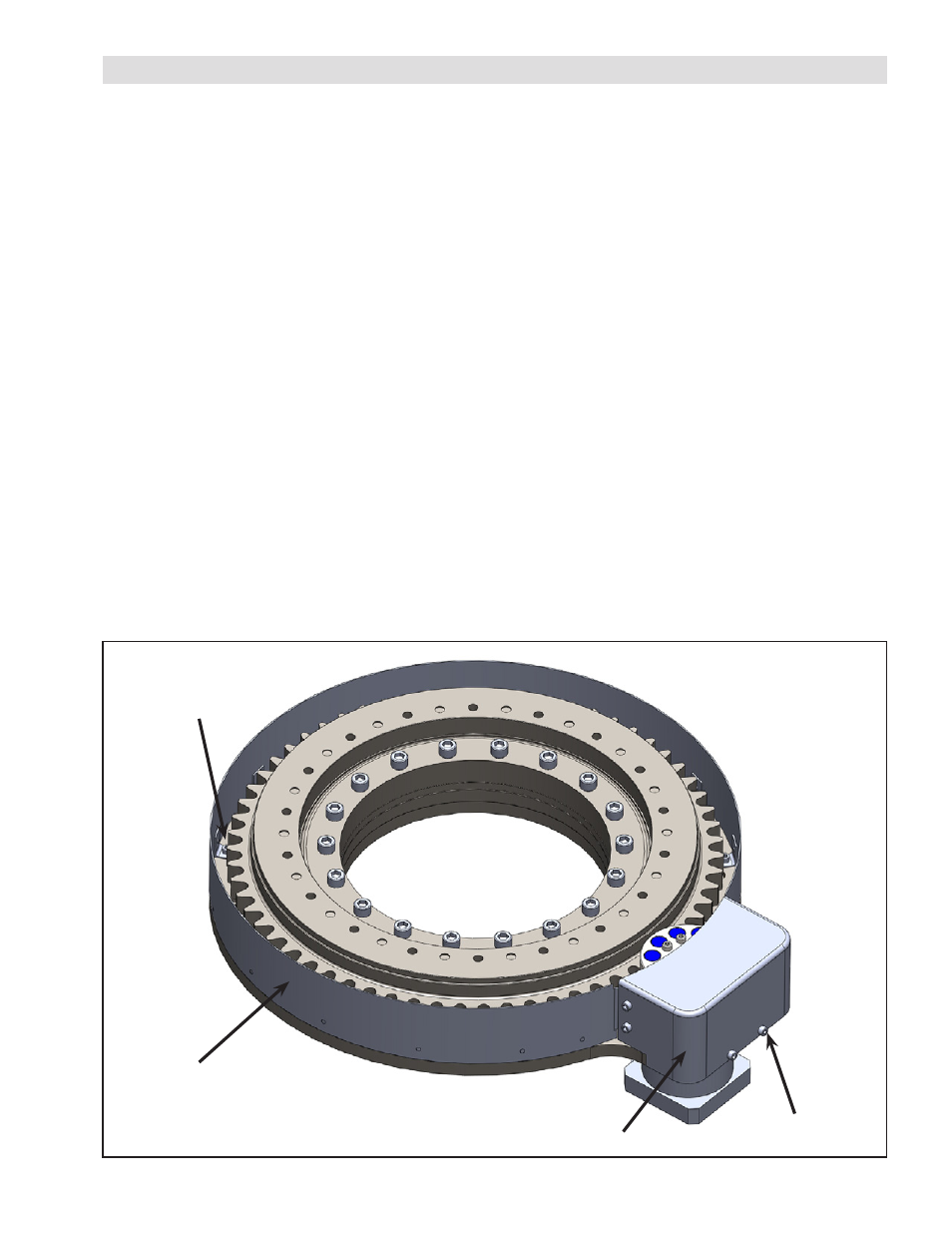
1. First remove the pinion guard by removing the six
M6 fasteners. See Figure 2.
2. To remove the gear guard, the multiple M6 fasteners
are accessible around and between the gear teeth
from the top. See Figure 2. Take extreme caution
near the gear teeth as they may be damaged by
contacting them with a tool.
3. Position the ring drive on the customer supplied
mounting surface. The size 400 can be lifted using
the threaded holes used to mount the dial plate. The
size 750, 1100 and 1500 have a pattern of M12
threaded holes on the inner race of the bearing that
can be used to lift the product.
4. Once the Ring drive is in location, install the M12
mounting bolts to secure to the mounting surface.
Tighten the bolts in a star pattern to ensure even
distribution of load. Nexen recommends using
grade 12 bolts for any application, although it is the
customer’s responsibility to ensure the mounting is
suitable for the system loads.
5. Reinstall the gear guard followed by the pinion
guard.
Motor Mounting
The motor mounting depends on the motor/gearbox
combination being used; please refer to the gearbox
manufacturer’s mounting instructions (included with
this document).
Dial Plate Mounting
The dial plate is designed to be piloted by a series of
dowel pins installed in the plate and that straddle the
male pilot on the ring drive. Drawings are available for
each specific size, which will aid in understanding the
method of piloting the dial plate.
The dial plates should be mounted using all available
holes. Again, tighten in a star pattern to ensure even
load distribution. It is the responsibility of the customer
to ensure the bolt grade and qty is sufficient for the
application.
Figure 2
Gear Guard
Fasteners
Gear Guard
Pinion Guard
Pinion Guard
Fasteners