Hg requirements, Hg installation – Nexen HG25 969043 User Manual
Page 5
5
FORM NO. L-21276-B-1213
HG REQUIREMENTS
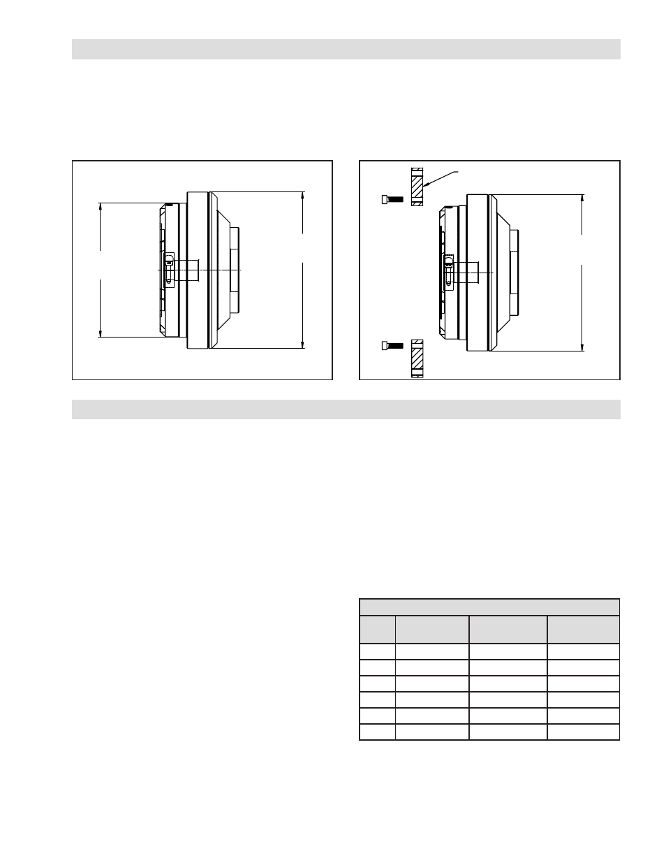
• The HG can be mounted in any orientation, however must meet the recommended mounting specifications found
later in this document.
• There are two pilot options on the HG product. If using the primary mounting pilot the product can be mounted
directly to the machine frame or pre-loader. If the secondary mounting pilot is desired, it will require a transition plate
as shown below.
PRIMARY
MOUNTING
PILOT
SECONDARY
MOUNTING
PILOT
Figure 1
SECONDARY
MOUNTING
PILOT
FRONT MOUNT APAPTOR RING
Figure 2
The order in which the HG is assembled to the motor and
machine is not critical, and should be done in whichever
order provides for the least amount of difficulty to the
machine assembler.
I
nstallatIon
of
M
otor
to
HG
1. Before installing the motor into the HG:
a. Wipe the motor shaft, pilot, and mounting face
clean. Wipe the internal pilot and motor mounting
face of the HG clean.
b. Ensure that the HG’s clamp collar is positioned
over the slotted portion of the motor shaft bore
such that the slots do not line up.
c. Remove clamp collar access set screw.
d. Insert the long blade of a hex bit (included) through
the clamp collar screw access hole in the motor
adapter and engage with the clamp collar screw
head.
2. Apply a serviceable thread locking compound to the
threads of the motor face mounting screws and a thin
film of anti-sieze compound to the motor shaft.
3. Slowly and gently guide the motor into the input of the
HG. During this part of the procedure, the weight of
the motor should be adequately supported. Never
allow the motor to be suspended from HG until the
shaft and pilot diameter are fully inserted.
4. Once the motor shaft and pilot are fully seated within
the HG input, tighten the motor face mounting screws
according to Table 1. After the motor face screws are
tightened the clamp collar screw can be tighten, also
according to Table 1.
HG INSTALLATION
Motor Fasteners
Size
HG Mounting
Screw Torque
Motor Mounting
Screw Torque
Clamp Collar
Screw Torque
17
32 in-lbs
28 in-lbs
18 in-lbs
25
32 in-lbs
28 in-lbs
18 in-lbs
Table 1
5. Once motor has been fully assembled to HG, remove
the hex bit from the clamp collar access hole and save
for future disassembly needs.
6. Reinstall clamp collar access set screw.