Bradford White IGE-199R-10N User Manual
Page 25
VI - TROUBLESHOOTING
(cont.)
QUICK REFERENCE DIAGNOSTIC POINTS
IMPORTANT SAFETY NOTES:
There are a number of (live) tests that are required when fault finding this product. Extreme care
should be used at all times to avoid contact with energized components inside the water heater.
Only trained and qualified service agencies should attempt to repair this product.
Remember, before checking for resistance readings, you should disconnect the power source
(unplug it) to the unit and isolate the item to be checked from the circuit.
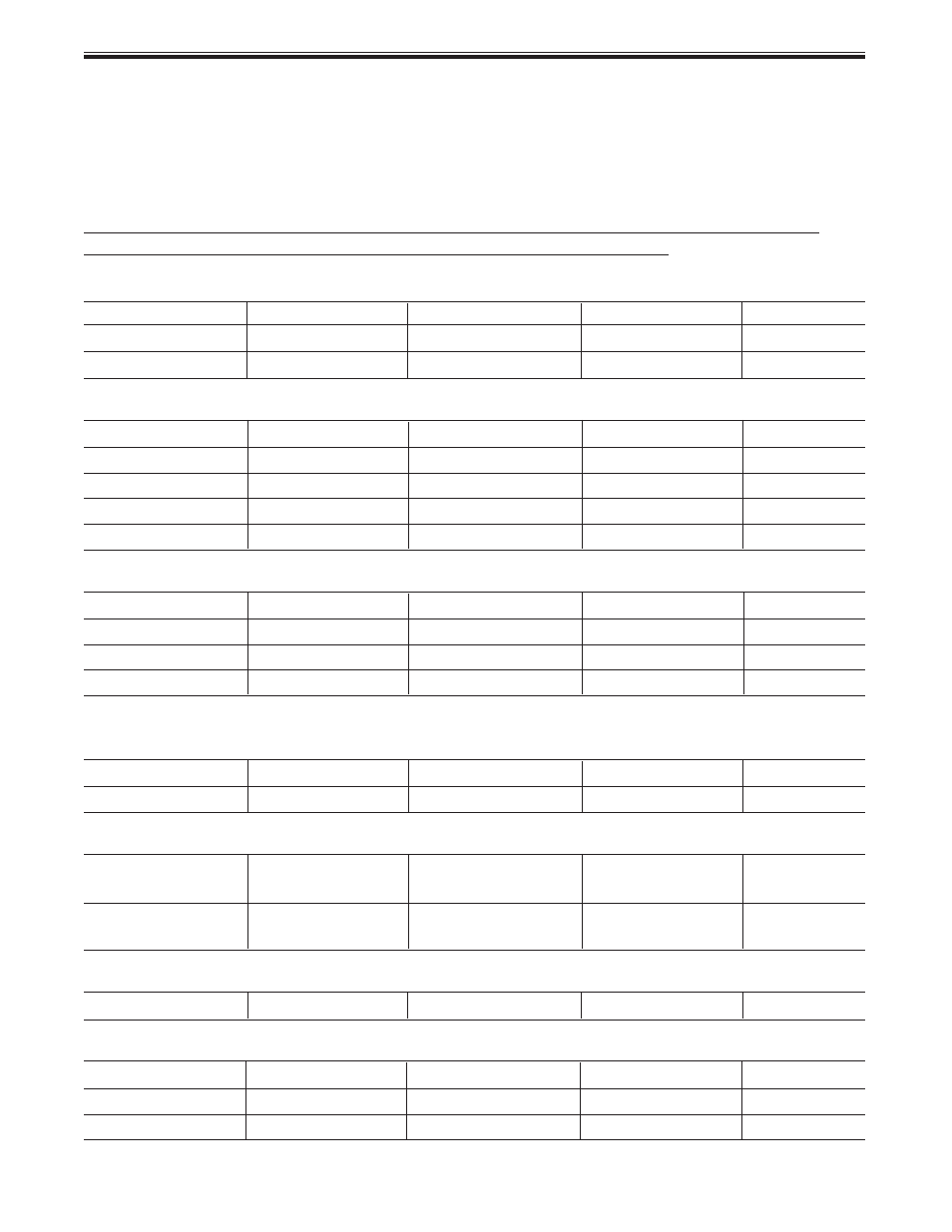
(TR) Transformer:
Wire color
Voltage
Resistance
Connector #
Pin #'s
Black ~ White
100 ~ 120 VAC
51 ~ 63 ohms
F9
1 ~ 2
Blue ~ Brown
110 ~ 120 VAC
51 ~ 63 ohms
F7
1 ~ 3
(SV0, SV1, SV2, SV3 and POV) Gas valve and Modulating solenoids: (Set meter above 2K)
(SV0) Pink ~ Black 80 ~ 100 VDC
1,8K ~ 2K ohms
E1
1 ~ 2
(SV1) Black ~ Yellow 80 ~ 100 VDC
1,8K ~ 2K ohms
E2
2 ~ 3
(SV2) Black ~ Blue 80 ~ 100 VDC
1,8K ~ 2K ohms
E3
2 ~ 4
(SV3) Black ~ Brown 80 ~ 100 VDC
1,8K ~ 2K ohms
E4
2 ~ 5
(POV) Pink ~ Pink
2 ~ 15 VDC
67 ~ 81 ohms
C2
3 ~ 4
(M) Water Flow Control Device Servo or Geared Motor:
Red ~ Blue
11 ~ 13 VDC
22 ~ 26 ohms
B2
9 ~ 10
Grey ~ Brown
4 ~ 6 VDC
N/A
B2
5 ~ 7
Grey ~ Yellow
N/A
N/A
B2
5 ~ 8
Grey ~ Orange
11 ~ 14 VDC
N/A
B2
5 ~ 6
NOTE: The grey wire listed above turns to black at B connector on the PCB, the orange wire turns to red.
(QS) Water Flow Sensor:
Black ~ Red
11 ~13 VDC
5.5K ~ 6.2K
B4
5 ~ 6
Yellow ~ Black
4 ~ 7 VDC
1 meg ~ 1.4 meg
B4
1 ~ 5
By-pass Flow Control:
Brown ~ White
2 ~ 6 VDC
Unit in operating
G4 ~ G5
4 ~ 5
Orange ~ White
mode
G2 ~ G5
2 ~ 5
Yellow ~ White
15 ~ 35K
G1 ~ G5
1 ~ 5
Red ~ White/Ground
3 ~ 5
(IG) Ignition System:
Grey ~ Grey
90 ~ 100 VAC
N/A
F8
2 ~ 3
(FM) Combustion Fan Motor:
Red ~ Black
6 ~ 45 VDC
N/A
A1
1 ~ 2
White ~ Black
6 ~ 45 VDC
9.2K ~ 9.4K
A1
2 ~ 4
Yellow ~ Black
11 ~ 13 VDC
3.5K ~ 3.9K
A1
2 ~ 3
Set your meter to the Hertz scale. Reading across the red and yellow wires at terminals 2 and 3 you
should read between 60 and 350 Hertz.
25