Bradford White U-PDX-75S-55FR-3N User Manual
Page 15
15
Venting continued-
TABLE 2 -VENT CONNECTOR LENGTHS
FOR 4” (10.2 cm) DIAMETER VENT PIPE
Terminating
# of 90
Elbows (excl.
vent term.)
Maximum straight
Length ft (m)
Min
straight
Length
ft (m)
48, 65 gal.
75 gal.
Through the Wall
1 95
(29.0) 85
(25.9)
10 (3.1)
Through the Wall
2 90
(27.4) 80
(24.4)
10 (3.1)
Through the Wall
3 85
(25.9) 75
(22.9)
10 (3.1)
Through the Wall
4 80
(24.4) 70
(21.3)
10 (3.1)
Through the Wall
5 75
(22.9) 65
(19.8)
10 (3.1)
Through the Roof
0 100
(30.5) 90
(27.4)
15 (4.6)
Through the Roof
1 95
(29.0) 85
(25.9)
15 (4.6)
Through the Roof
2 90
(27.4) 80
(24.4)
15 (4.6)
Through the Roof
3 85
(25.9) 75
(22.9)
15 (4.6)
Through the Roof
4 80
(24.4) 70
(21.3)
15 (4.6)
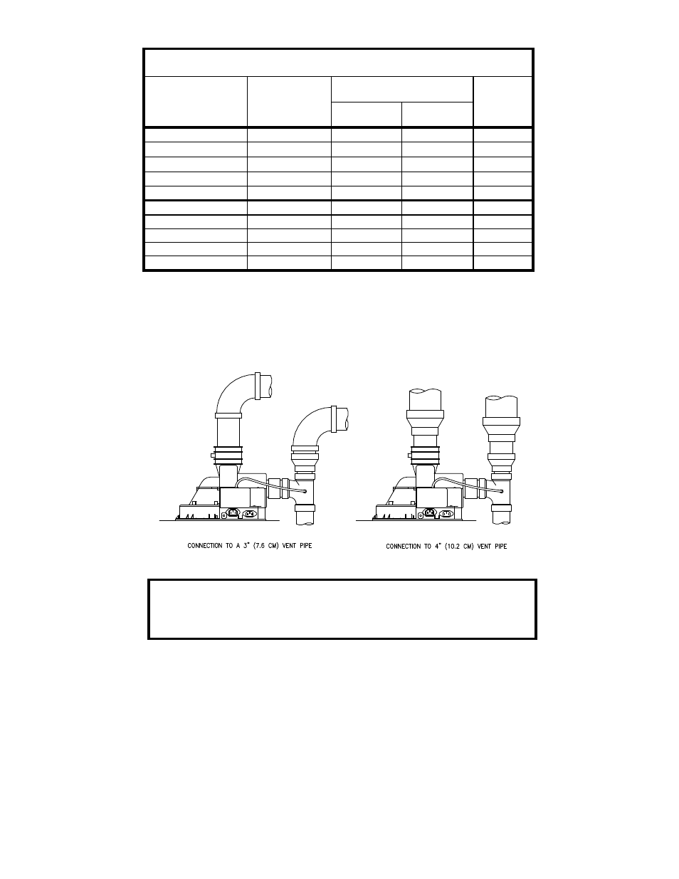
NOTE: When using 4” (10.2 cm) vent pipe, use two 4” (10.1 cm) to 3” (7.6
cm) reducers for each portion of the vent. One reducer is installed just
after the blower and the other reducer is used just prior to exiting the
building. Exit the building wall with 3” (7.6 cm) vent pipe using the 3”
(7.6 cm) 90
vent terminal supplied. Two 45 elbows are equivalent to one
90
elbow.
Figure 2
IMPORTANT
All of the Venting connections must be leak checked with a soap and
water solution upon initial start up of the water heater. Any leaks must
be repaired before continuing operation of the water heater.