Installation – B&C Technologies HI Series Commercial User Manual
Page 25
25
Installation
External Chemical Supplies
The supply compartment on the B&C HI-
125 model is located on the left side of the
machine. Supply cups can be accessed by
open the dispenser lid. The supply cups can
be removed and filled as desired. Supply
compartments are numbered 1,2,3,4 and 5
from the rear of the machine to the front.
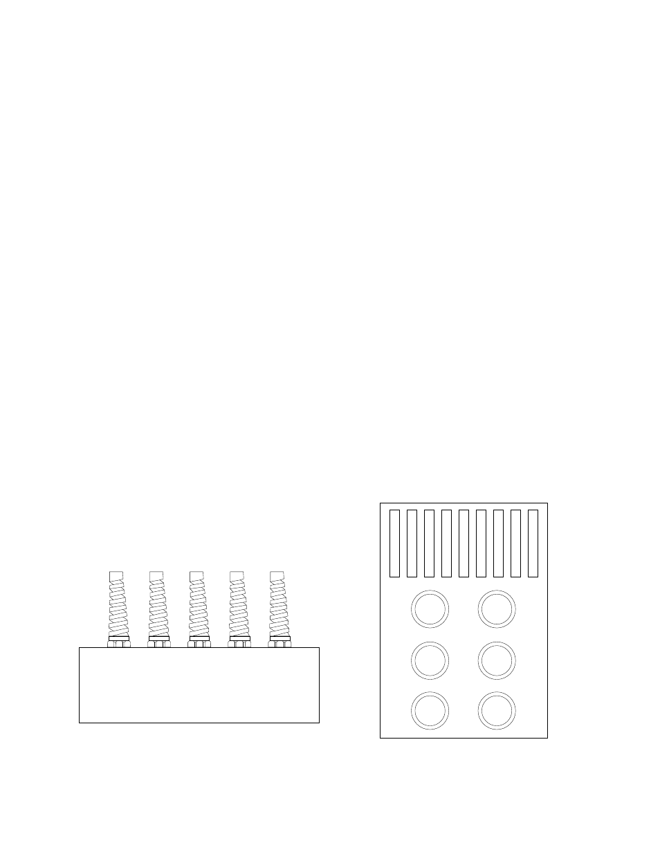
External supply connections for the B&C HI
washer-extractors are located on top of the
supply dispenser. Hose connections should
be made via the strain relief. See figure.
1.
Remove plugs from base. See
figure. Plugs are assembled inside
the tubing ring.
2.
Install strain relief, included in the
seal nut.
3.
Insert tubes through base. Do not
remove cups. Tube should extend
into the plastic cup, with the
exception of the softener tube,
which should be routed to
the outside of the cup.
4.
Tighten the seal nut to prevent
tubing from escaping the assembly.
External supply connections for the B&C
HI-85 washer-extractors are located on rear
of the machine at the vacuum breaker.
Hose connections should be made via the
threaded connectors. See figure.
1.
Remove plugs from base. See
figure.
2.
Install the supplied chemical
nipple, using teflon tape.
3.
Insert tubes onto the nipples, using
small hose clamps or wire ties to
prevent the hose from slipping off.
The chemical flush water valve (relay 12)
should be used with each chemical signal
(see the EL6 programming manual for
details).
HI-125 Strain Relief for
Supply Connections
HI-85 Supply Connections