Vrm series – Vintage Cellars VRM Series Split System User Manual
Page 2
VRM SERIES
US Cellar Systems / 3070 Golden Ave, Long Beach, CA 90806 / www.uscellarsystems.com
(562) 513-3017 phone and fax / [email protected]
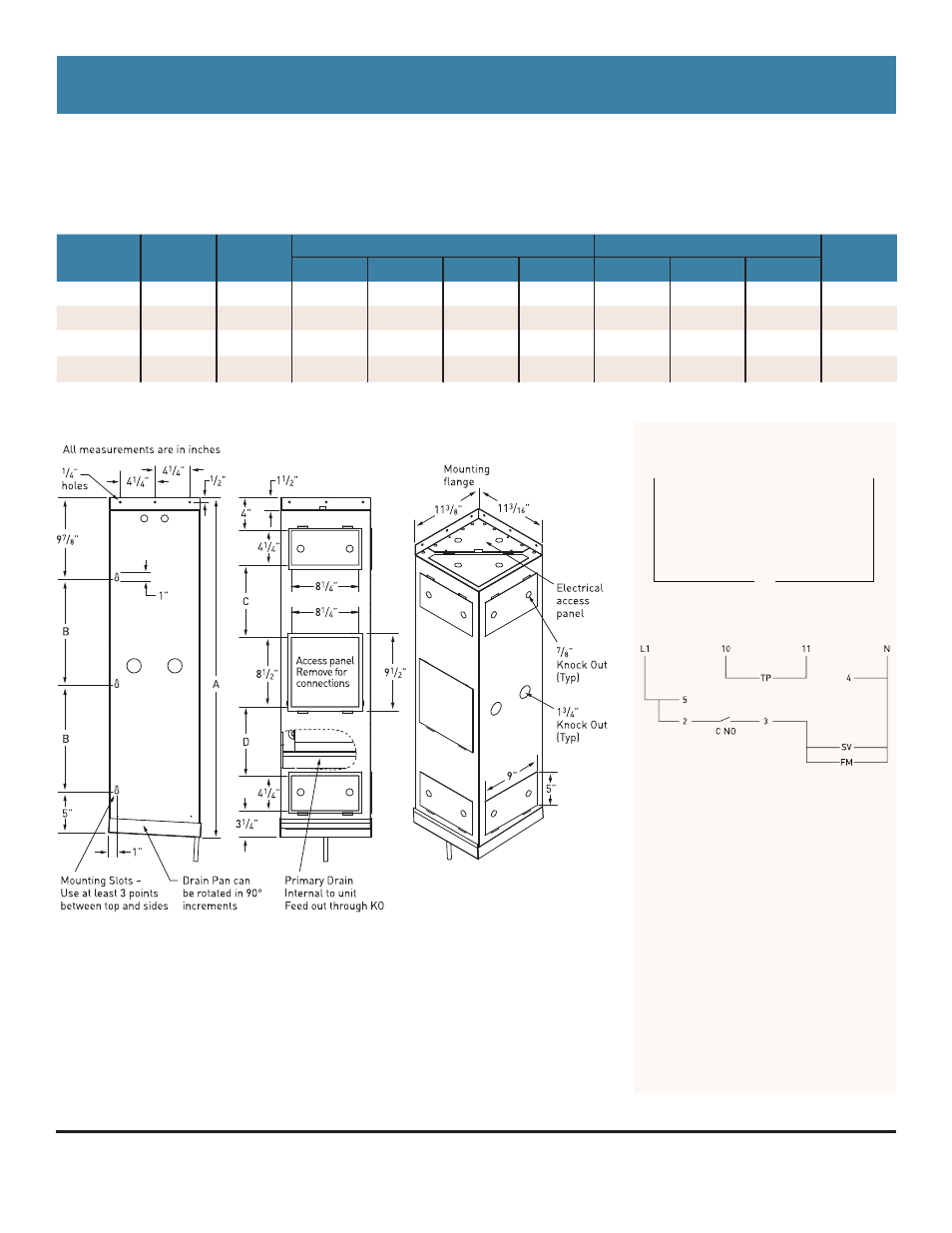
VRM Fan Coil Specifications
MODEL
CFM
AMPS
115 V
DIMENSIONS
CONNECTIONS
APPROX
SHIP WT.
A
B
C
D
LIQUID
SUCTION
DRAIN
VRM 25
220
0.77
41.50”
13”
8.81”
8.44”
0.38”
0.38”
0.50”
48 lbs
VRM 35
260
0.77
45.50”
15”
9.31”
11.94”
0.38”
0.38”
0.50”
50 lbs
VRM 50
335
0.77
47.50”
16”
9.31”
13.94”
0.38”
0.50”
0.50”
59 lbs
VRM 65
420
1.85
51.50”
18”
N/A
N/A
0.38”
0.50”
0.50”
63 lbs
Mounting Diagrams
Field Wiring
L1
115 V Line Voltage
N Neutral
SV
Solenoid Valve
FM Fan Motor
TP
Temperature Probe
Back of Controller Connections
10
Temperature Probe
11
Temperature Probe
4 Neutral
5
115V Line Voltage
2
Jumper from 5
3
Switch Leg to Fan Coil
C NO Internal normally open contact
Fan Coil Wiring
Condensing Unit Wiring
L1
CU
N
• It is best to use the larger coil whenever possible.
• If using a smaller coil a suction line accumulator must be used
• Smaller coils can cause the system to run a lower humidity
• Expansion valve and liquid line solenoid valve standard
• For air flow into and out of the unit, at least one access door
must be removed from each end
• Connections at coil do not indicate refrigeration line size. See
system information for line sizing
Due to continuing engineering improvements, specifications are subject to change without notice.
March 29, 2012 10:03 PM