Humidistat installation – Vintage Cellars Active Humidity WhisperKOOL User Manual
Page 5
www.whisperkool.com | Page 5
Mounting With a Wall Mount Plate
1.
Make sure the power to humidistat electrical wires is shut off at the main electrical box before installing the unit.
2.
Position the wall mount plate on the wall or junction box and ensure the plate is level and covers the junction
box completely.
3.
Pull the electrical wires through the hole in the wall mount plate.
4.
Drill holes in the wall through the 2 mounting holes in the back of the wall plate as shown in Figure 8 and insert
anchors into the holes.
5.
Then drill holes through the 2 mounting holes in the wall plate where the humidistat will attach and insert
anchors into the holes.
6.
Pull the electrical wires through the hole at the terminal block.
7.
Fasten the wall plate with 2 screws through the mounting holes.
8.
Then fasten the humidistat to the wall plate with screws through the mounting holes.
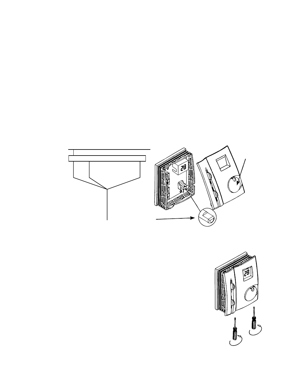
Reattaching the Cover
1.
Move both slide controls to the bottom position.
2.
Align the humidistat adjustment shaft horizontally as shown in Figure 10.
Correct Humidistat Settings
1.
Rotate the dial to the desired humidity level.
2.
Set the bottom selector switch to the Humid setting.
3.
Set the top selector switch to the Hi setting.
3.
In order for the humidistat dial to fit on the shaft, it must be aligned with the
pointer above the dial.
4.
Carefully attach the top cover and ensure the cover locks into place by pushing
down on the top and then pushing inward toward the wall.
5.
Attach the screws again at the bottom of the cover and tighten into place as
shown in Figure 11.
6.
Check that the adjustment dial and slide controls can be moved smoothly,
otherwise remove the cover and check the alignment of the dial and the
adjustment shaft and slide controls.
Electrical Connection
1.
Connect the electrical wires to the corresponding terminals on the terminal block following the circuit diagram
inside the top cover of the unit. See Figure 9
2.
Connect the white wire to the N terminal, the red wire to the 1 terminal and the black wire to the L terminal on
the humidistat.
L
1
2
7
6
5
N
RED
BLA
CK
HUMIDISTAT
COOLING UNIT
WHITE
HUMIDISTAT INSTALLATION
Figure 10 -
Make sure the Dial is Vertical and the
Adjustment Shaft is Horizontal
Figure 9
Figure 11