Tjernlund Auto-Draft FSAD & VSAD Series Inducers 8504090 Rev 11/00 User Manual
Page 8
7
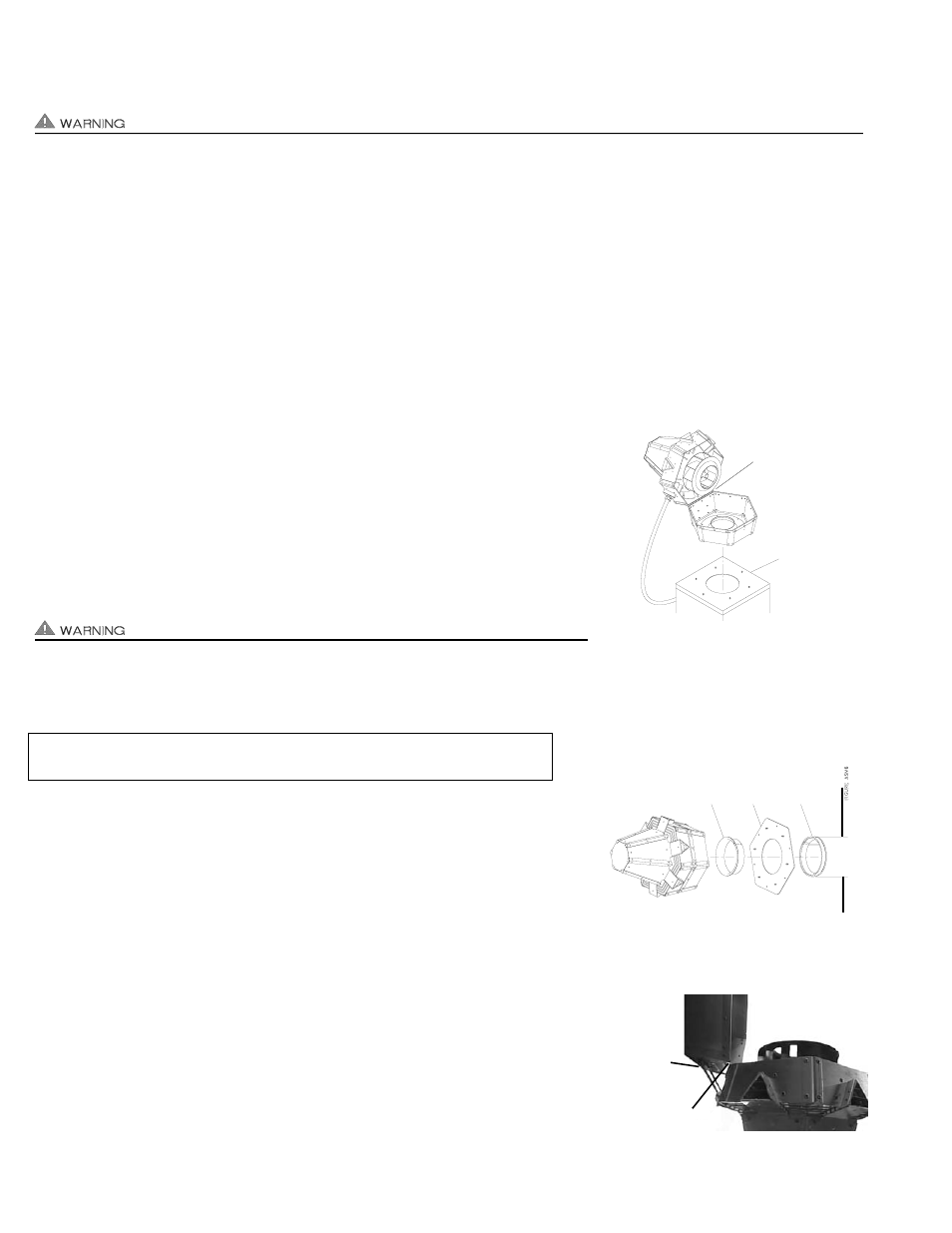
5. Seal around the venter base and the Mounting Plate with hi-temp silicone. Make sure it is watertight and no water can slip in
between the venter base and Mounting Plate. Do not block the (6) corner drain holes, (See Diagram D).
INSTALLATION ON ROOF CURB OR MASONRY CHIMNEY
Auto-Draft® motor side is heavy. Housing hinge pin should be removed for easier installation. Support Venter base when
removing hinge pin. When removing motor side, use extreme caution so internal parts such as the impeller are not damaged.
IF USING AUTO-DRAFT® MOUNTING PLATE FOR ROOF CURB / MASONRY CHIMNEY INSTALLATION:
1. Lay a bead of hi-temp silicone on the Auto-Draft® Venter Mounting Plate side without mounting studs.
2. Secure the Mounting Plate to the roof curb making sure that opening in the Mounting Plate aligns up with opening in roof curb.
3. Lay a bead of hi-temp silicone close to the outer edge of Venter base. Do not block the (6) corner drain holes, (See Diagram D).
4. Align Mounting Plate studs with holes in Venter base and secure the Auto-Draft® to the Mounting Plate with (6) provided nuts.
5. Seal around the Venter base and the Mounting Plate with hi-temp silicone. Make sure it is watertight and no water can slip in
between the Venter base and Mounting Plate. Do not block the (6) corner drain holes, (See Diagram D).
IF MOUNTING TO ROOF CURB / MASONRY CHIMNEY WITHOUT AUTO-DRAFT® MOUNTING PLATE:
1. Use Auto-Draft® Venter base as a template to mark six spots for bolting to roof curb. Drill
(6) holes for 5/16-18 stainless steel bolts, installer supplied.
2. Lay a bead of hi-temp silicone close to the outer edge of Auto-Draft® Venter base. Do not
block the (6) corner drain holes, (See Diagram D).
3. Bolt Auto-Draft® Venter base with stainless steel fasteners to curb, (See Diagram E).
4. Seal around the Venter base and the Mounting Plate with hi-temp silicone. Make sure it is
watertight so water cant slip in between the Venter base and curb or chimney cap.
Do not block the (6) corner drain holes, (See Diagram D).
INSTALLATION ON SIDE WALL
Auto-Draft® motor side is heavy. Housing hinge pin should be removed for easier
installation. Support Venter base when removing hinge pin. When removing motor
side, use extreme caution so internal parts such as the impeller are not damaged.
1. Vent pipe should extend far enough through exterior wall to attach Inlet collar.
2. Insert the Inlet Collar through the Mounting Plate and slide the Inlet Collar with
Mounting Plate into vent pipe, (See Diagram F).
3. Secure the Inlet Collar to vent pipe with self tapping stainless steel screws, installer
supplied. Make sure the screws are long enough to adequately secure Inlet Collar
and Auto-Draft® to vent pipe.
4. Push Mounting Plate against wall with flat side pointing down. Make sure flat side is
level and mark (6) mounting holes on wall using Mounting Plate as a template. Drill
out and tap holes as necessary for appropriate stainless steel lag bolts.
5. Place a bead of hi-temp silicone on the Mounting Plate back side and firmly push against
wall. Secure Mounting Plate to wall with appropriate lag bolts, installer supplied, consid-
ering Auto-Draft® Venter weight. Adequately support and secure vent pipe.
6. Lay a bead of hi-temp silicone close to the outer edge of Auto-Draft® Venter base.
7. IMPORTANT: Housing hinge must face down when mounting on a side wall. Align
Mounting Plate studs with holes in Auto-Draft® Venter base and secure the
Auto-Draft® to the Mounting Plate with provided nuts, (See Diagram G).
DIAGRAM E
DIAGRAM G
USER-SUPPLIED
CHIMNEY CAP
OR CURB
DIAGRAM F
INLET
COLLAR
MOUNTING
PLA
TE
PIPE
SIDE W
ALL
HOUSING
HINGE MUST
POINT DOWN
SUPPORT
HANDLE
BRACKET
HINGE PIN & MOTOR
SIDE SHOULD BE
REMOVED FOR
EASIER INSTALLATION
Tjernlund’s Optional ETL approved WMK-8,10,12 kits may be utilized to maintain
clearances to combustibles.