Tjernlund DB-2 Duct Booster 8504030 Rev B 09/00 User Manual
Page 3
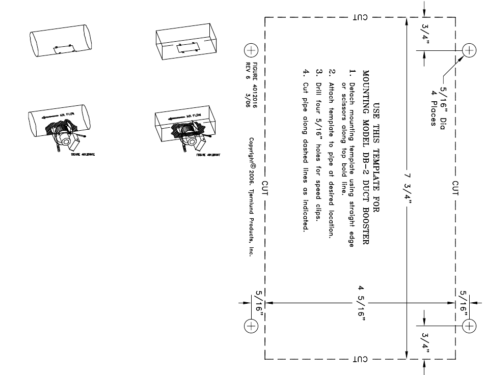
2. Attach speed clips to vent pipe and align with four holes drilled in step 1.
3. Insert DUCT BOOSTER
®
in the slot with the adjustable damper curved plate
above blower wheel pointing in the direction of air flow. The front flange goes
inside the duct and the side flanges go on the outside. Bend the flanges to
conform to the duct. Secure DUCT BOOSTER® to duct utilizing speed clips
and screws provided. Use wrench to tighten nut behind electrical box.
INSTALLATION RESTRICTIONS
Do not install the DUCT BOOSTER® where temperatures of air within the duct
exceed 200
O
F. This temperature would only rarely be found on a forced warm
air system but could exist close to the furnace on a gravity warm air system.
Locating the DUCT BOOSTER® near the outlet end of a duct will provide the
most efficient performance.
The DUCT BOOSTER® must be installed with the motor shaft horizontal. It
can be installed on the bottom or top of a horizontal duct or any side of a
vertical duct.
CAUTIONS
1. Failure to install, maintain and/or operate the DUCT BOOSTER® in accor-
dance with manufacturer’s instructions may result in conditions which can
produce bodily injury and property damage.
2. Disconnect power supply when making wiring connections and servicing the
DUCT BOOSTER®. Failure to do so may result in personal injury and/or
equipment damage.
3. Make certain the power source is adequate for the DUCT BOOSTER®
requirements.
ADJUSTMENT OF VARI-DRAFT DAMPER
The DUCT BOOSTER® is shipped from the factory so that the maximum CFM
is established when unit is installed. To reduce the CFM, slide the Vari-Draft
damper so it will penetrate into duct further. Adjustments should be made prior
to installing the DUCT BOOSTER® into duct.