Tjernlund SS2G SideShot (Discontinued) 8504075 Rev 1 11/98 User Manual
Page 6
INSTALLATION TOOLS REQUIRED
•
Nut Runner Set
•
Drill w/Bits
•
Combination Wrench Set
•
Screwdriver Set
•
Wire Cutter/Stripper
•
Draft Gauge
•
Reciprocating Saw
5
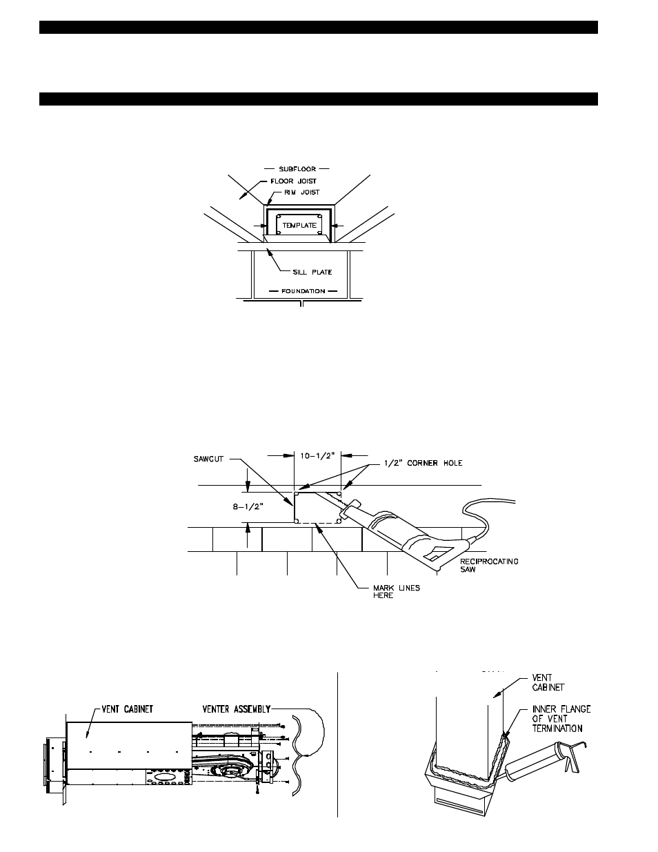
DIAGRAM B
2. Verify that wall penetration will not come in contact with concealed wiring or plumbing. Using 1/2” bit, drill pilot holes noted on
each side of the template from inside through rim-joist, wall board, siding, etc., keeping drill bit perpendicular to the wall. 1/2" bit
must be long enough to penetrate through exterior.
3. Remove template from rim-joist and attach to building exterior, aligning pilot hole markings on template with holes previously
created in Step #2.
4. Drill remaining (4) corner holes noted on the template through the building exterior. Remove the template and mark lines from
the
outside edge of the holes drilled, forming a rectangle.
5. Using reciprocating saw and appropriate blade, cut a rectangular opening through the rim joist, wall board, siding, etc., on the
lines marked in step 4. The rectangular opening should be no larger than 10-1/2" in width by 8-1/2" in height, (See Diagram C).
6. Knock out block material exposing rectangular opening through the wall.
DIAGRAM C
INSTALLING SS2G VENT CABINET
1. a) Fold SS2G Vent Cabinet template (Page 14) along dashed line and attach between the floor joists ensuring that it is snug
against the sill plate and centered between the floor joists. Follow same procedure if floor trusses are used, (See Diagram B).
b) If the SS2G is not being installed between floor joists, attach the template to the wall it will be exiting ensuring it is level.
NOTE: For easy one person installations, remove (9) screws from rear and bottom of vent cabinet. Slide venter assembly out of
SS2G cabinet and set aside being careful not to damage housing. After SS2G cabinet is secured to the outside wall, and
the vibration isolation mount is installed to the inside wall, replace venter assembly and (9) screws, (See Diagram D).
7. Apply two beads of exterior rated caulk approximately 3/8" in width at the seam of the outside casing of the SS2G Vent Cabinet
and on the inner flange of the Vent Hood Termination, (See Diagram E).
DIAGRAM D
DIAGRAM E