Tjernlund SS1R SideShot (Discontinued Version - Pre UC1 Universal Control) 8504046 Rev 05/95 User Manual
Page 12
ELECTRICAL WIRING OF SS1-R ON OIL EQUIPMENT
All wiring from the SS1-R to the appliance must be appropriate Class 1 wiring as follows: installed in rigid metal conduit, intermedi-
ate metal conduit, rigid non-metallic conduit, electrical metallic tubing, Type MI Cable, Type MC Cable, or be otherwise
suitably protected from physical damage.
The electrical contact ratings for the diaphragm Fan Proving Switch and High Limit are as follows:
FAN PROVING SWITCH
HIGH LIMIT
6.2 Amps (full load) at 120 VAC
10 Amps (full load) at 120 VAC
36 Amps (locked rotor) at 120 VAC
60 Amps (locked rotor) at 120 VAC
OIL SOLENOID VALVE
RELAY, R1
0.115 Amps at 120 VAC
0.10 Amps at 120 VAC (Coil)
12 Amps (full load) at 124 VAC (Contacts)
60 Amps (locked rotor) at 125 VAC (Contacts)
The Fan Proving Switch, High Limit Switch, Oil Solenoid Valve and R1 Relay are not suitable for loads which exceed the above
limits.
PREPARATION FOR SYSTEM WIRING
Make sure all power is disconnected from the furnace before attempting to install the SS1-R. Failure to do so can cause electrical
shock resulting in personal injury or death.
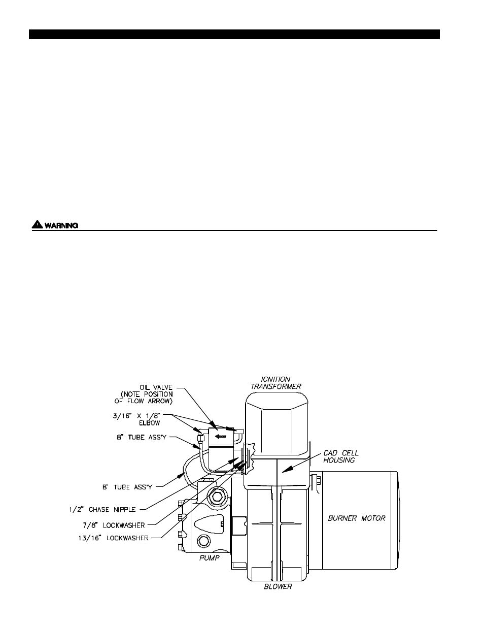
INSTALLATION OF OIL SOLENOID VALVE (DIAGRAM P)
1. Apply pipe sealant to the Elbows and attach the Elbows to the valve in the positions shown.
2. Place the Chase Nipple through the Cad Cell housing with the 13/16” Lockwasher on the inside of the housing and the 7/8”
Lockwasher on the outside of the housing as shown below.
3. Thread the Chase Nipple into the valve passing the wires of the Valve through the Chase Nipple.
4. Connect one 8” Tube Assy. from the pump to the Valve and the remaining 8” Tube Assy. from the Valve to the Nozzle Line
paying attention to the direction of flow as shown.
5. Thread wires (two) from solenoid valve through Cad Cell housing of burner to the existing junction box.
11
DIAGRAM P