Tjernlund SS1R SideShot (Discontinued) with UC1 Universal Control (Version X.06) 8504117 Rev B 02/06 User Manual
Page 14
13
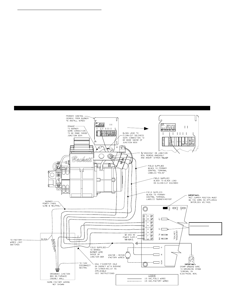
6. For "F" (-OBF-XXX, -OPF-XXX and etc.) series oil furnaces: Remove a knock-out slug from the existing junction box mounted to the burner
(see Diagram R). A 7/8" diameter bushing or strain-relief must be installed in the hole formed by removing the slug.
A.
In addition to L1, Neutral and ground that must be supplied to the SS1R UC1 control board, five wires are to be installed from the oil
furnace to the SS1R Side Wall Vent System. Refer to Diagram R wiring instructions below.
B.
Attach L1 (115V) and Neutral wires from a nominal 115VAC power source to L & N on the SS1R UC1 control board. This power should
be routed through a disconnect so that power to the SS1R can be turned off remotely if necessary. Additionally, all wire should be run
through the appropriate conduit per NEC standards as noted in step 1.
C.
A ground wire will need to be supplied between the system ground and the grounding lug in the SS1R electrical box.
D.
A neutral wire will need to be installed from the oil furnace line neutral to the terminal labeled "2" on the UC1 control board.
E.
Inside the burner mounted junction box, remove the leads from the primary control terminals labeled "Burner/Motor" and "Valve".
F.
Install a field-constructed wire between the lead removed from the terminal labeled "Burner/Motor" (step E above) and the UC1 control
board terminal labeled "M". The connection to the burner motor lead will require a special male ¼" quick connect (Amp Manufacturing
part # 2-520102-2 (insulated male spade)). Do NOT cut any wires on the existing burner. Also, the wire connection to the "Burner/Motor"
lead should be made inside the burner junction box and should be covered and concealed by the primary control once it is replaced.
G.
Install a field-constructed wire between the terminal labeled "Burner/Motor" (step E above) and the UC1 control board terminal labeled "1".
The connection to the primary control will require a female ¼" quick connect (Amp Manufacturing part # 2-520856-2).
H.
Install a field-constructed wire between the lead removed from the terminal labeled "Valve" (step E above) and the UC1 control board
terminal labeled "4". The connection to the "Valve" lead will require a special male ¼" quick connect (Amp Manufacturing part #
2-520102-2 (insulated male spade)). Do NOT cut any wires on the existing burner. Also, the wire connection to the "Valve"
lead should be made inside the burner junction box and should be covered and concealed by the primary control once it is replaced.
I.
Install a field-constructed wire between the terminal labeled "Valve" (step E above) and the UC1 control board terminal labeled "3".
The connection to the primary control will require a female ¼" quick connect (Amp Manufacturing part # 2-520856-2).
J.
IMPORTANT: The Call Jumper between J1 and J2 on the UC1 board in SS1R must be removed. The RED Voltage Jumper on UC1
board must be in the 115V position.
DIAGRAM R
FIELD WIRING TO RHEEM, RUUD, OR WEATHERKING -OBF-XXX & OPF-XXX MODEL OIL BURNING FURNACES
IMPORTANT:
CALL JUMPER MUST
BE REMOVED.