Diagram q – Tjernlund SS1R SideShot (Discontinued) with UC1 Universal Control (Version X.06) 8504117 Rev B 02/06 User Manual
Page 13
For "F" series oil furnaces (-OBF-XXX, -OPF-XXX & etc.): Drill a 1" diameter hole into the junction box side of the furnace
wall, allowing for adequate clearance from electrical components. (Do not drill the hole at or near the junction box.) Use caution
when drilling into the furnace so existing wiring and components are not damaged. The five wires connecting the Rheem, Ruud
or Weatherking oil-fired furnace to the SS1R power venter must be routed through this new hole. When the hole is complete,
install a 1" diameter bushing. Some wires will route to the burner junction box and some will route to the main junction box on
the furnace wall. If electrical conduit is not going to be used to the junction boxes, then a mechanical strain relief must be used
where wires pass into the junction boxes (Note: There may be additional room in the existing strain relief(s) of the junction
boxes to add additional wires. Check the specifications for the strain relief.).
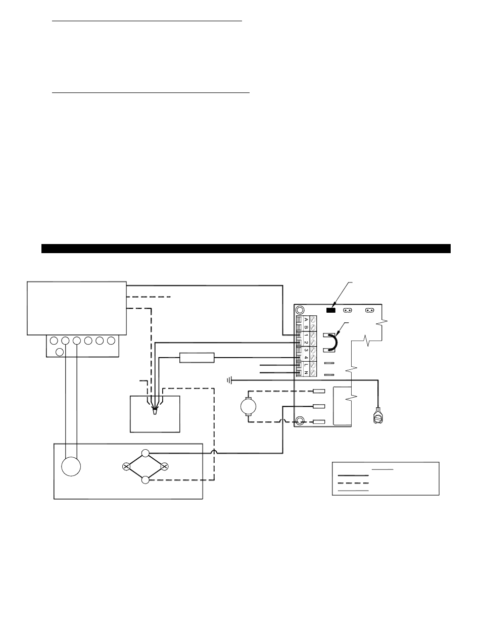
5. For "D"(-OBD-XXX, -OPD-XXX and etc.) series oil furnaces, remove the wire-nuts which secure the Orange to Black wires
(burner control) and White wires (line neutral) of the primary control (see Diagram Q).
A.
In addition to the L1, Neutral and ground that must be supplied to the SS1R UC1 control board, four wires are to be
installed from the oil furnace to the SS1R Side Wall Vent System. Refer to Diagram Q and instructions below for wiring.
B.
Attach L1 (115V) and Neutral wires from a nominal 115VAC power source to L & N on the UC1 control board. This power
should be routed through a disconnect so that power to the SS1R can be turned off remotely if necessary. Additionally, all
wire should be run through the appropriate conduit per NEC standards as noted in step 1.
C.
A ground wire will need to be installed between the system ground and the grounding lug in SS1R electrical box.
D.
A neutral wire will need to be installed from the oil furnace line neutral to the terminal labeled "2" on the UC1 control
board. Note: The existing wire nut (which connects all the line neutrals together) is full and a new wire cannot be added
to it. A new (larger) wire-nut will have to be installed and this will require that the neutral wire is cut and stripped.
E.
Route a wire to connect the orange lead on the primary furnace control to the UC1 control board terminal labeled "1".
F.
Last, route a wire between the Beckett burner motor and ignition transformer to the UC1 control board terminal labeled "M".
G.
The RED Voltage Jumper on UC1 board in SS1R must be in the 115V position.
12
50/60 Hz
SUPPLY
115 VAC
SPADE TERMINAL IN ELECTRICAL BOX.
GROUND
CRIMP GROUND WIRE TO GROUNDING
IMPORTANT:
C
F
F
R
W
G
Y
WHITE
BLACK
ORANGE
BECKET BURNER
TO BURNER
MOTOR
BLACK
B / W
TO FUSE
DISCONNECT
YELLOW
YELLOW
NEUTRAL
JUNCTION BOX
TO FACTORY-WIRED
LIMIT SWITCHES
VIA JUNCTION BOX
GROUNDED
LEGEND:
LOW VOLTAGE
115 VAC, FIELD-WIRED
115 VAC, FACTORY-WIRED
VENTER MOTOR
(FACTORY-WIRED)
SENSOR
TO IGNITION
TRANSFMR
OIL VALVE
IMPORTANT:
XL
J1
J2
115V
DRY
24V
D/N 9183047-5
CALL
JUMPER
PRIMARY CONTROL
RED JUMPER POSITION MUST BE THE SAME
AS APPLIANCE INTERLOCK VOLTAGE.
UNIV
E
R
S
A
L CO
NT
RO
L
XN
TO FLAME
NM
T
R
M
DIAGRAM Q
FIELD WIRING TO RHEEM, RUUD, OR WEATHERKING -OBD-XXX & OPD-XXX MODEL OIL BURNING FURNACES