Tjernlund HS3,4,5 Series with UC1 Universal Control (Version X.02) 8504111 Rev 09/02 User Manual
Page 6
5
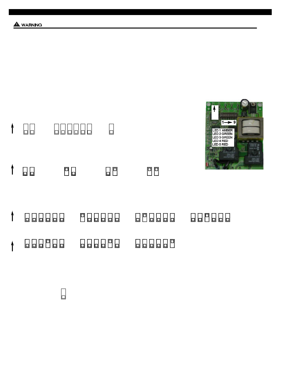
PRE / POST PURGE AND PROVER STATUS CHECK DIP SWITCH SETTINGS
Remove power to UC1 and heating equipment when installing, servicing or changing dip switch settings. Failure to do so may result in
personal injury and/or equipment damage. LED #5 (RED) should not be on if 115 VAC supply power is removed from the control.
Pre-purge
Used for a Venter with longer vent runs to get draft fully established throughout the vent system prior to burner ignition. Also benefi-
cial for negative pressure prone environments. IMPORTANT: Pre-purge settings must be shorter than flame sensor lockout time
unless wired prior to flame sensor (i.e. aquastat / thermostat).
Post-purge
A Venter post-purge has been factory set at 2 minutes. Confirm that dip switch #5 is in the up or "on" position. A longer post-purge
may be necessary for longer vent runs or high heat retention, refractory lined combustion chambers. A shorter post-purge may be desired
for shorter vent runs or when using the UC1 to control a combustion air In-Forcer.
Pre-Purge
Post-Purge
Prover Status
Check Activated
DIP SWITCH NUMBERING
1
ON
ON
ON
PRE-PURGE SETTINGS
ON
POST-PURGE SETTINGS
ON
P1 & P2 FAN PROVER SAFETY CIRCUIT “OPEN” UPON APPLIANCE CALL
The Prover Status Check is activated from the factory. When activated the UC1 Universal Control
checks across P1 & P2 safety circuit (Venter Fan Prover) to verify that the Fan Prover switch is
“Open” upon a call for heat and not stuck “Closed”. IMPORTANT: This must always be in the
down “Activated” position when side wall venting.
Prover Status
Check Activated
2
3
4
5 6
7 8
9
9
1 2
1 2
1 2
1 2
0 Seconds
15 Seconds
30 Seconds
60 Seconds
PRE-PURGE SETTINGS
4
3
4
8
6
5
7
3
5 6 7 8
3 4 5 6 7 8
3
7
5
4
6
8
4
3
4
8
6
5
7
3
5 6 7 8
3 4 5 6 7 8
4 Minutes
8 Minutes
16 Minutes
1 Minute
0 Seconds
30 Seconds
2 Minutes
P1 & P2 FAN PROVER SAFETY CIRCUIT "OPEN" UPON APPLIANCE CALL