Tjernlund HSJ, 1, 2 Series with UC1 Universal Control (Version X.02) 8504106 Rev 08/02 User Manual
Page 15
14
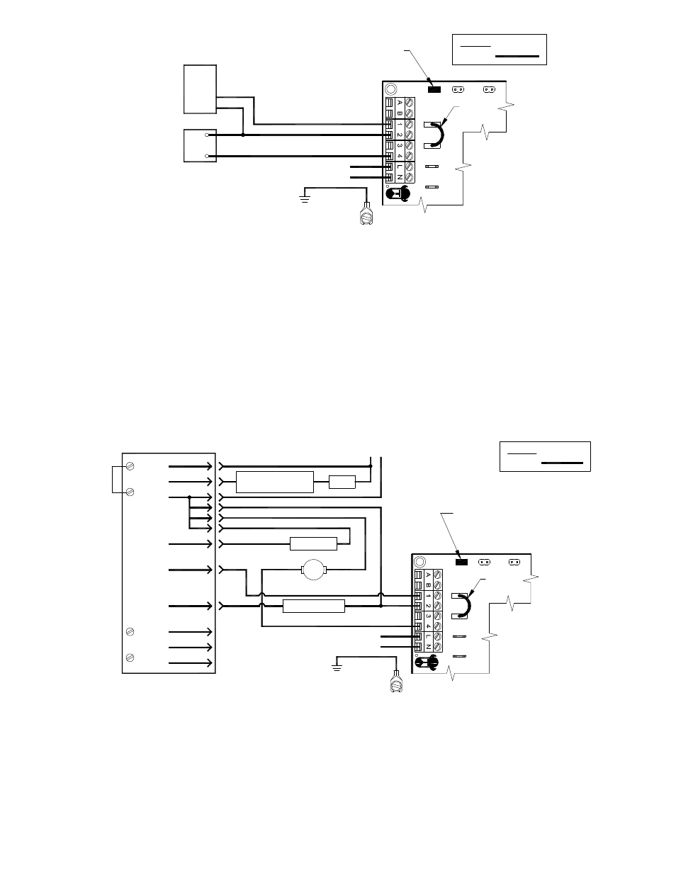
UC1 UNIVERSAL CONTROL CONNECTED TO A HONEYWELL R7184 SERIES OR EQUIVALENT
PRIMARY CONTROL WITH A LINE VOLTAGE THERMOSTAT OR AQUASTAT
Burner
Alarm
Cad Cell
A
Interrupted
Intermittant
Motor
A
IGNITION TRANS
BURNER MOTOR
R
Oil Valve
Limit
R7184
L1
T
T
L2
OIL VALVE
115 VAC
60 Hz
SUPPLY
Limit
24V
DRY
115V
XL
UNIVERSAL CONTROLLER
XN
J1
J2
RED JUMPER POSITION MUST BE THE SAME
AS APPLIANCE INTERLOCK VOLTAGE.
IMPORTANT:
D/N 9183046-6
115 VAC
LEGEND:
CALL
JUMPER
Ignitor
Line Voltage Thermostat
or Aquastat Control
Low Voltage
Jumper
50/60 Hz
SUPPLY
115 VAC
SPADE TERMINAL IN ELECTRICAL BOX.
GROUND
CRIMP GROUND WIRE TO GROUNDING
IMPORTANT:
1. Disconnect burner motor wire off the R7184.
2. Connect burner motor terminal of R7184 to #1 on UC1 terminal block.
3. Connect #2 on UC1 terminal block to L2 or N.
4. Connect #4 on UC1 terminal block to burner motor wire removed from R7184.
5. Make sure RED voltage jumper on UC1 is on 115V.
6. Connect 115 VAC supply voltage to L & N terminals on UC1. Crimp Ground wire to grounding spade terminal in UC1.
Important: Installer must supply overload and disconnect protection.
7. If not previously completed, connect ground from UC1 whip to grounding stud in Venter. Connect Black and White leads
from UC1 whip to Venter motor leads. Connect Blue and Yellow leads from UC1 whip to Fan Prover switch terminals in
Venter. Yellow lead should be on switch terminal closest to Venter junction box wall.
UC1 UNIVERSAL CONTROL CONNECTED TO A GAS OR OIL BURNER WITH AN AQUASTAT
XN
R
UNIVERSAL CONTROLLER
LINE VOLTAGE OIL BURNER
PRIMARY CONTROL, BURNER
L1
N
XL
J1
J2
115V
DRY
24V
AQUASTAT
B2
B1
C1
C2
L1
L2
D/N 9183046-7
115 VAC
LEGEND:
CALL
JUMPER
RELAY OR GAS VALVE
50/60 Hz
SUPPLY
115 VAC
RED JUMPER POSITION MUST BE THE SAME
IMPORTANT:
AS APPLIANCE INTERLOCK VOLTAGE.
SPADE TERMINAL IN ELECTRICAL BOX.
GROUND
CRIMP GROUND WIRE TO GROUNDING
IMPORTANT:
CAUTION:
WHEN INTERLOCKING WITH AQUASTAT DO NOT DISCONNECT BURNER MOTOR
FROM PRIMARY CONTROL / CAD CELL RELAY.
1. Disconnect B1 from L1 of oil burner primary control, burner relay or hot of gas valve and reconnect to #1 on UC1 terminal block.
2. Connect #2 on UC1 terminal block to B2 or N.
3. Connect #4 on UC1 terminal block to the L1 on line voltage oil burner primary control, burner relay or gas valve.
4. Make sure RED voltage jumper on UC1 is on 115V.
5. Connect 115 VAC supply voltage to L & N terminals on UC1. Crimp Ground wire to grounding spade terminal in UC1.
Important: Installer must supply overload and disconnect protection.
6. If not previously completed, connect ground from UC1 whip to grounding stud in Venter. Connect Black and White leads
from UC1 whip to Venter motor leads. Connect Blue and Yellow leads from UC1 whip to Fan Prover switch terminals in
Venter. Yellow lead should be on switch terminal closest to Venter junction box wall.
NOTE: If burner primary control goes out on lockout, the Venter will continue to run as long as a call for heat is present.