Tjernlund HSJ, 1, 2 Series with UC1 Universal Control (Version X.02) 8504106 Rev 08/02 User Manual
Page 12
11
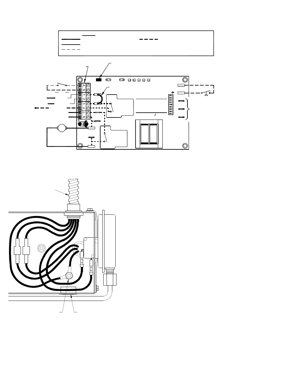
IMPORTANT:
RED JUMPER POSITION MUST BE THE SAME
AS APPLIANCE INTERLOCK VOLTAGE.
CALL
RELAY
INTERLOCK
COMMON
NEUTRAL
PRODUCTS,
INC.
MOTOR
1 H.P. MAX @ 115 VAC
SUPPLY
115 VAC
50/60 Hz
R
TJERNLUND
9183006
NO
MTR
M
MOTOR
RELAY
N
COM
NO
115 VAC
24 VAC
D/N 1303958-1
DO NOT SUPPLY VOLTAGE
TO "A" OR "B".
DO NOT SUPPLY POWER!
5 VDC BOARD-GENERATED POWER
HOT
24 VAC
USER-PROVIDED
CALL SWITCH
LINE
OR
"DRY"
OR
115V
J2
COM
24V
DRY
LEGEND:
115 VAC
5
POST-PURGE SETTINGS
FOR TJERNLUND
TO P1, P2, C, GND
AUXILIARY
OR F. DOING SO
WILL DAMAGE THE
CONNECT POWER
OPEN PROVER OPTION
(9)
(3 - 8)
9
7
8
6
CONTROL.
DEVICES. DO NOT
F
GND
ON
LED1
PRE-PURGE SETTINGS
LED5 LED4
LED2
LED3
(1 - 2)
2
4
3
1
C
P1
P2
PROVER
J1
XL
XN
115 OR 24 VAC FROM CALL JUMPER
OR USER-PROVIDED VOLTAGE
FROM TERMINAL 3 TO 4 WITH CALL
JUMPER REMOVED
K2
K1
APPROVED
MAC1E OR MAC4E
JUMPER
RED
RED
GREEN
GREEN
AMBER
WARNING: Disconnect power supply from the UC1 and heating equipment when making wiring connections and servicing the
Venter. Failure to do so may result in personal injury and/or equipment damage. LED #5 (RED) should be off with
power removed.
GREEN
BLUE
YELLOW
WHITE
BLACK
GREEN
WHITE
BLACK
GROUNDING STUD
2 FT. WHIP FROM UC1
HSJ, 1, 2 ELECTRICAL BOX
FAN PROVER
INSERT PROVIDED
HOLE PLUG
D/N 2201018J
UC1 UNIVERSAL CONTROL WIRING SCHEMATIC
The Ground lead, Venter motor and Fan Prover leads are factory connected to the UC1 circuit board. Venter Ground, motor and Fan
Prover wiring connections are made at the free end of the 2 foot whip in HS-Series junction box.
WIRING CONNECTIONS FROM UC1 UNIVERSAL CONTROL MADE
IN HS-SERIES JUNCTION BOX
1. Connect ground from UC1 whip to grounding stud in Venter.
2. Connect Black and White leads from UC1 whip to Venter motor leads.
3. Connect Blue and Yellow leads from UC1 whip to Fan Prover switch
terminals in Venter. Yellow lead should be on switch terminal closest
to Venter junction box wall.
4. Insert provided hole plug in HS-Series junction box in opening
opposite UC1 whip.
MULTIPLE APPLIANCE INTERLOCKS
To interlock with one additional 24/115 VAC heater add the MAC1E. It
is a stripped down auxiliary board version of the UC1 and is powered by
and communicates with the UC1 through a factory wired whip.
To interlock more than two 24/115 VAC heaters, add the MAC4E for a
total of up to 5 heaters. It is powered by and communicates with the
UC1 through a factory wired whip.
To interlock a millivolt water heater and a 24/115 VAC furnace or boiler,
add the WHKE and MAC1E.
MILLIVOLT INSTALLATIONS
Each millivolt appliance interlocked with the UC1 must have its own
WHKE kit installed. The WHKE Gas Pressure Switch actuates the
Venter through the A - B Dry contacts. The Linear Limit switch disables
the heater in the event of a venting malfunction. IMPORTANT: Each
millivolt appliance interlocked with the UC1 must have its own Linear
Limit spill switch.