Tjernlund HSJ, 1, 2 Series with UC1 Universal Control (Version X.06) 8504106 Rev C 07/05 User Manual
Page 9
INSTALLATION
VENT SYSTEM TERMINATION
Before installing Power Venter determine location of vent system termination.
TOOLS REQUIRED
• Saber Saw or Cement Drill
• Drill
• 1/8” and 1/4” Drill Bits
• Wood or Masonry Chisel
• Blade Screwdriver or 1/4” Nut Driver • Wire Cutter/Stripper
NOTE: Termination of a Side Wall Vent System with a device other than the Tjernlund VH1 Series Vent Hood could affect system
performance and result in a possible safety hazard. Consult Vent Hood instructions for complete installation details.
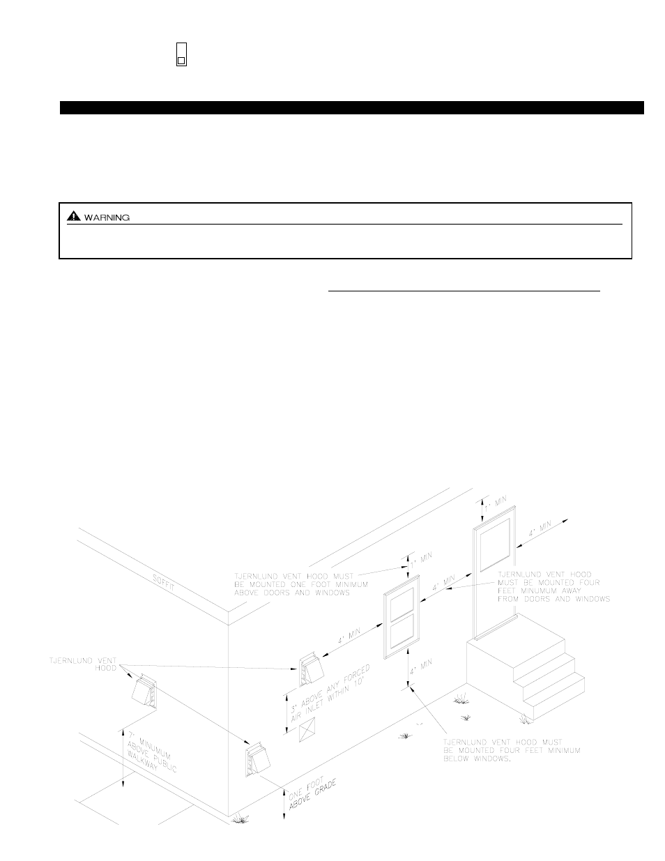
VENT HOOD TERMINATION CODE REQUIREMENTS FOR U.S. INSTALLATIONS
If possible, locate the Vent Hood on a wall that does not face the direction of prevailing winds. This will diminish the possi-
bility of appliance interruption during periods of extreme winds and prevent oil odors caused by backdrafts.
If possible, locate the Vent Hood no closer than 3 feet from an inside corner of an L-shaped structure.
Terminate the vent system so that proper minimum clearances are maintained as cited in the latest edition of the National Fuel Gas
Code (NFPA # 54) and the latest edition of NFPA #211, or as follows:
• Not be less than 7 feet above grade when located adjacent to public walk ways.
• At least 3 feet above any forced air inlet located within 10 feet.
• At least 4 feet below, 4 feet horizontally from or 1 foot above any door, window or gravity air inlet into any building.
• At least 12 inches above grade.
• So that the flue gases are not directed so as to jeopardize people, overheat combustible structures or enter buildings, and
• Not less than 2 feet from an adjacent building.
6
For oil installations do not terminate HS-Series Power Venters on vinyl siding because temperatures can easily exceed 150
0
F.
The SideShot® is the only Tjernlund Power Venter recommended for termination on vinyl siding when using oil.
P1 & P2 PRE-CYCLE FAN PROVER STATUS CHECK
The Pre-Cycle Prover Status Check is activated from the factory. When activated the UC1
Universal Control checks across P1 & P2 safety circuit (Venter Fan Prover) to verify that the Fan
Prover switch is “Open” upon a call for heat and not stuck “Closed”.
Pre-Cycle
Prover Status
Check Activated
9