Tjernlund GPAK-JT,1T 8504034 Rev 11/97 User Manual
Page 7
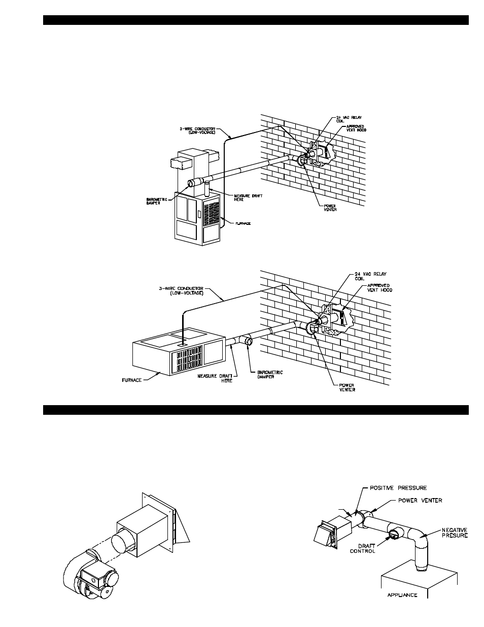
DRAFT CONTROL INSTALLATION
When installing any GPAK-Series Side Wall Venting System on a fan assisted furnace a barometric draft control must be added. The
draft control provides pressure relief to neutralize over-drafting and allows a means of draft adjustment for optimum furnace efficiency.
By adjusting the draft control the installer can obtain the furnace manufacturer’s recommended draft setting.
Install the vent pipe and draft control as shown in the diagrams below. The draft control should connect to a tee off of the furnace flue
outlet.
The GPAK-Series Venting System may only be used with furnaces capable of being chimney vented. It is not suitable for use on
high-efficiency, condensing models.
POWER VENTER MOUNTING
1. Slide the outlet of the Power Venter over the inlet of the Vent Hood and connect them together using the provided screws,
(See Diagram D). For the HTPV Corrective Action Program, if you are unable to make a direct connection to the Vent Hood, a
maximum 1 foot length of type “B” vent pipe may be installed between the outlet of the Power Venter and Vent Hood. NOTE: Seal
all seams after Power Venter discharge to assure no flue gas leakage, (See Diagram E). No elbows may be installed on discharge
side of Power Venter for the HTPV Corrective Action Program.
6
DIAGRAM D
DIAGRAM E
(HORIZONTAL FURNACE)
(UPFLOW FURNACE)
MAXIMUM ONE ONE FOOT SECTION OF “B” VENT
ALLOWED BETWEEN POWER VENTER AND VENT
HOOD FOR THE HTPV CORRECTIVE ACTION
PROGRAM. ALL SEAMS ON THE POSITIVE SIDE
OF POWER VENTER TO BE SEALED WITH HIGH
TEMPERATURE SILICONE CAULK