Tjernlund GPAK-JT,1T 8504034 Rev 11/97 User Manual
Page 11
COMBUSTION AIR
Adequate combustion air is vital for proper combustion and for safe venting. Likewise, for proper GPAK performance, adequate com-
bustion air must be available to the appliance. Many installers assume adequate combustion air is present, especially in older homes.
In some cases this is a false assumption, because many older homes have been made "tight" due to weatherization. Size the com-
bustion air opening(s) into the appliance room as outlined NFPA 54/NFPA 211. Tjernlund’s IN-FORCER
TM
engineered combustion air
intakes provide a convenient, interlocked way to supply combustion air to the utility room. When installing a GPAK it is not necessary
to supply any more combustion air than normally required when conventional venting.
SAFETY INTERLOCK / COMBUSTION AIR TEST
The Power Venter Fan Proving Switch is designed to disable the appliance gas valve upon Power Venter failure only! It is not
designed and cannot replace, regular vent system inspection, appliance servicing and combustion testing.
1. Close all doors and windows of the building. If the appliance is installed in a utility room or closet, close the entrance door to this
room. Close fireplace dampers.
2. Turn on clothes dryer and all exhaust fans such as range hoods, bathroom exhausts and whole house fans to maximum speeds.
(Do not operate a fan used strictly for Summer exhausting).
3. Following the appliance manufacturer’s instructions, place the appliance in operation, set thermostat for continuous operation.
4. Allow fans and appliance to operate for 5 minutes.
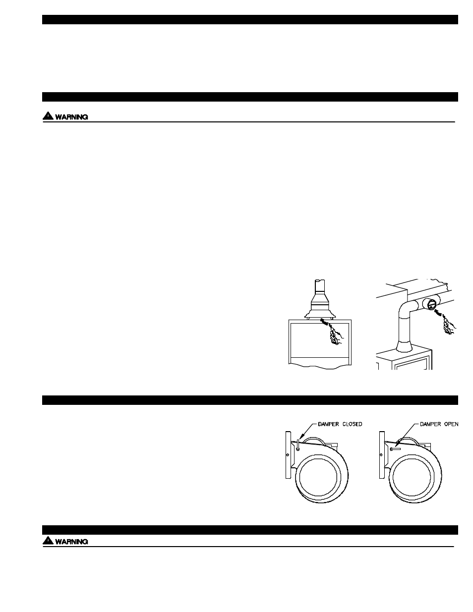
5. Test for spillage at the appliance draft hood, draft control or draft diverter relief opening using the flame of a match, candle or
smoke from a cigarette, cigar or pipe and determine the following:
A) The flame or smoke is being drawn into the draft hood, draft control or draft diverter.
B) The main burner is burning properly, i.e. no floating, lifting or flashback. Adjust the primary air shutter(s) and Power Venter air flow
adjustment as required.
C) If the appliance is equipped with high and low flame controlling or flame
modulation, check for proper main burner operation at low flame,
(See Diagram G).
If the draw of the flame or smoke appears to be excessive, follow the “Air
Flow Adjustment” procedure outlined below.
6. Sign and date these instructions to verify that the safety interlock /
combustion air test was completed. These instructions must
remain on premises.
SIGN:____________________________________
DATE:_____________________
AIR FLOW ADJUSTMENT
1. With all exhaust fans and appliance operating as instructed in “Safety
Interlock/Combustion Air Test”, set the Air Flow Adjustment by loosening
locknut and turning rod handle. CAUTION: HANDLE MAY BE HOT, USE
PLIERS TO MOVE HANDLE. Position of rod handle indicates the position
of Air Flow Adjustment inside housing.
2. Using pliers, move handle towards minimum draft setting until spillage is
detected at draft hood relief opening, then re-open Air Flow Adjustment
just enough to eliminate spillage.
3. Lock Air Flow Adjustment at desired setting by tightening locknut.
4. Return appliance, doors, windows, exhaust fans and fireplace dampers to
their previous conditions of use.
TROUBLESHOOTING
The following guide is intended to be used if a problem occurs during the use of the GPAK side wall vent system. At several steps
throughout the guide you will come in close contact with 115 Volts. Extreme caution must be exercised to prevent injury. If you
are unable to determine the defective part with the use of this guide, call your Tjernlund distributor or Tjernlund Products direct at
1-800-255-4208 for further assistance.
10
DIAGRAM G