Tjernlund 950-8804 UC1 Universal Control Board Kit (Version X.04) 8505017 Rev A 05/03 User Manual
Page 6
4
UC1 INSTALLATION
Do not mount the UC1 junction box on a heat source that exceeds 140oF (60oC). Examples of improper mounting surfaces
include vent pipe, top of heater casing or any place where radiant or convective heat would cause the junction box temperature to
exceed 140oF. The UC1 is intended for indoor installation only.
Using the key hole slots on the back of the UC1 junction box as a template, mark 4 holes on the mounting surface, drill pilot holes
if necessary, and secure junction box using provided screws.
The UC1 has a 2 foot whip that contains a ground lead and the leads to power the Venter motor and connect to the Fan Prover. If
it is desirable to mount the UC1 more than 2 feet from the Fan Proving Switch an additional electrical junction box and appropriate
length of conduit will be necessary. Any added wire should be 14 gage and a pig tail should be added to each ground wire con-
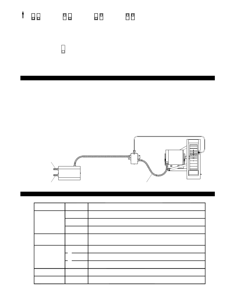
nection so that each electrical junction box is grounded. See diagram below for a typical UC1, Fan Prover and Venter installation.
TYPICAL UC1, FAN PROVER AND VENTER INSTALLATION
ELECTRICAL WIRING
ELECTRICAL SPECIFICATIONS
FAN PROVER
VENTER
UC1
ALUMINUM SENSING TUBE, 4 FT. MAXIMUM LENGTH
2 FT. MAXIMUM LENGTH UNLESS ADDITIONAL
CONDUIT AND J-BOX ARE ADDED
INSTALLER-SUPPLIED CONDUIT
AND 3 WIRE, MINIMUM 14 GAGE
INSTALLER-SUPPLIED
115 VAC CONNECTION
BURNER INTERLOCK
CONNECTION
INSTALLER-SUPPLIED
POWER
REQUIREMENTS
EXTERNAL
POWER SWITCHING
CAPACITY
J1 / J2
JUMPER
SAFETY
CIRCUIT
ADD VENTER MOTOR
LOAD PLUS 1/2 AMP
FOR UC1 LOAD
EXTERNAL
CALL TRIGGER
METHODS
J1 / J2
P1 / P2
L / N
3 TO 4
T-BLOCK
T-BLOCK
(RELAY K1)
XL / XN
UC1 CONTROL
M & MTR
(RELAY K2)
T-BLOCK
A / B
24V
1 / 2
115V
1 / 2
OR
OR
USED TO JUMP CALL HOT (24 VAC) OR CALL LINE (115 VAC) FROM TERMINAL 1 TO TERMINAL 3.
CONNECTED TO FAN PROVER.
1 mA @ 5 VDC. DO NOT SUPPLY POWER HERE.
REMOVE J1-J2 JUMPER IF A DIFFERENT VOLTAGE SOURCE IS PROVIDED TO TERMINAL 3.
120 VAC ±10 %, 50/60 Hz
MOTOR - 1 H.P. MAX. @ 120 VAC, 50/60 Hz
USER-PROVIDED 24 VAC AT TERMINALS 1 & 2. 1 = CALL HOT, 2 = COMMON. CONTROL
REQUIRES 5 mA @ 24 VAC TO TRIGGER. MOVE RED VOLTAGE JUMPER TO "24V" LOCATION.
3 mA @ 5 VDC. MOVE RED VOLTAGE JUMPER TO "DRY" LOCATION. DO NOT SUPPLY POWER.
USER-PROVIDED CONTACT CLOSURE FROM A TO B. SIZE CONTACT CLOSURE TO HANDLE
GENERAL PURPOSE - 15A @ 120 VAC, 50/60 Hz
DURING OPERATION THE CONTROL USES 50 mA MAX @ 120 VAC
MOTOR - 1 H.P. MAX. @ 120 VAC, 50/60 Hz
150 mA MAX @ 120 VAC, 50/60 Hz
CAN ONLY BE CONNECTED TO TJERNLUND-SPECIFIED AUXILIARY DEVICE
CIRCUIT PROTECTION PROVIDED BY INSTALLER
GENERAL PURPOSE - 15A @ 120 VAC, 50/60 Hz
RESISTIVE - 10A @ 28 VDC PILOT DUTY - 470 VA
USER-PROVIDED 115 VAC AT TERMINALS 1 & 2. 1 = CALL LINE, 2 = NEUTRAL. CONTROL
REQUIRES 1 mA @ 115 VAC TO TRIGGER. MOVE RED VOLTAGE JUMPER TO "115V" LOCATION.
P1 & P2 FAN PROVER SAFETY CIRCUIT “OPEN” UPON APPLIANCE CALL
Prover Status
Check Activated
The Prover Status Check is activated from the factory. When activated the UC1 Universal Control
checks across P1 & P2 safety circuit (Fan Prover) to verify that the Fan Prover switch is “Open”
upon a call for heat and not stuck “Closed”. IMPORTANT: This must always be in the down
“Activated” position when side wall venting. When using the PS1505 Fan Prover in conjunc-
tion with a draft inducer on a vertical termination stack, “natural draft” may be sufficient to keep
Prover contacts closed prior to a call for heat by an interlocked appliance. This is the only condi-
tion where this safety feature should be deactivated. Push up or “ON” to deactivate.
9
ON
PRE-PURGE SETTINGS (SEE “PRE-PURGE” ON PAGE 3 PRIOR TO SETTING PRE-PURGE)
1 2
1 2
1 2
1 2
0 Seconds
5 Seconds
20 Seconds
35 Seconds
POST-PURGE SETTINGS