Tjernlund 950-8804 UC1 Universal Control Board Kit (Version X.04) 8505017 Rev A 05/03 User Manual
Page 11
9
Alarm
A
Violet
0.3 A, AC
OIL VALVE
R
A
Blue
Orange
F
F
White
T
Black
Red/White
T
115 VAC
BURNER MOTOR
IGNITION TRANS
500 VA
10 FLA / 60 LRA
Line Voltage Thermostat
60 Hz
SUPPLY
J2
UNIVERSAL CONTROLLER
XN
XL
J1
RED JUMPER POSITION MUST BE THE SAME
AS APPLIANCE INTERLOCK VOLTAGE.
IMPORTANT:
115V
DRY
24V
D/N 9183046-3
115 VAC
LEGEND:
CALL
JUMPER
Limit
or Aquastat Control
Low Voltage
Jumper
50/60 Hz
SUPPLY
115 VAC
SPADE TERMINAL IN ELECTRICAL BOX.
GROUND
CRIMP GROUND WIRE TO GROUNDING
IMPORTANT:
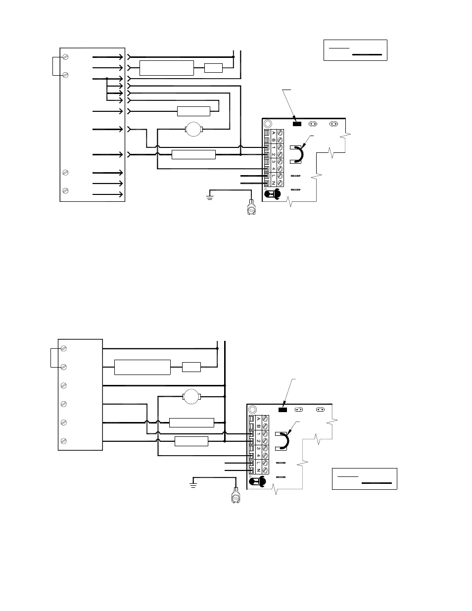
1. Disconnect burner motor wire off the Orange on Carlin.
2. Connect burner motor terminal Orange of Carlin to #1 on UC1 terminal block.
3. Connect #2 on UC1 terminal block to L2 or N
4. Connect #4 on UC1 terminal block to burner motor wire removed from Orange of Carlin.
5. Make sure RED voltage jumper on UC1 is on 115V.
6. Connect 115 VAC supply voltage to L & N terminals on UC1. Crimp Ground wire to grounding spade terminal in UC1.
Important: Installer must supply overload and disconnect protection.
7. If not previously completed, connect ground from UC1 whip to Venter ground. Connect Black and White leads from UC1 whip
to Venter motor leads. Connect Blue and Yellow leads from UC1 whip to Fan Prover switch. Prover Leads are not polarity sensitive.
UC1 UNIVERSAL CONTROL CONNECTED TO A HONEYWELL R7184 SERIES OR EQUIVALENT
PRIMARY CONTROL WITH A LINE VOLTAGE THERMOSTAT OR AQUASTAT
Burner
Alarm
Cad Cell
A
Interrupted
Intermittant
Motor
A
IGNITION TRANS
BURNER MOTOR
R
Oil Valve
Limit
R7184
L1
T
T
L2
OIL VALVE
115 VAC
60 Hz
SUPPLY
Limit
24V
DRY
115V
XL
UNIVERSAL CONTROLLER
XN
J1
J2
RED JUMPER POSITION MUST BE THE SAME
AS APPLIANCE INTERLOCK VOLTAGE.
IMPORTANT:
D/N 9183046-6
115 VAC
LEGEND:
CALL
JUMPER
Ignitor
Line Voltage Thermostat
or Aquastat Control
Low Voltage
Jumper
50/60 Hz
SUPPLY
115 VAC
SPADE TERMINAL IN ELECTRICAL BOX.
GROUND
CRIMP GROUND WIRE TO GROUNDING
IMPORTANT:
1. Disconnect burner motor wire off the R7184.
2. Connect burner motor terminal of R7184 to #1 on UC1 terminal block.
3. Connect #2 on UC1 terminal block to L2 or N.
4. Connect #4 on UC1 terminal block to burner motor wire removed from R7184.
5. Make sure RED voltage jumper on UC1 is on 115V.
6. Connect 115 VAC supply voltage to L & N terminals on UC1. Crimp Ground wire to grounding spade terminal in UC1.
Important: Installer must supply overload and disconnect protection.
7. If not previously completed, connect ground from UC1 whip to Venter ground. Connect Black and White leads from UC1 whip
to Venter motor leads. Connect Blue and Yellow leads from UC1 whip to Fan Prover switch. Prover Leads are not polarity sensitive.
UC1 UNIVERSAL CONTROL CONNECTED WITH A CARLIN 40200, 42230, 48245, 50200, 60200
SERIES OR EQUIVALENT AND A LINE VOLTAGE THERMOSTAT OR AQUASTAT