Optimum clearance requirement, Alternate construction requirements – Thetford 9100 Series Installation Manual User Manual
Page 6
A.G.A. and CGA certification permits installing the refrigerator with zero (0) inches clearance between
the refrigerator and any adjacent walls. This certification does not specify any maximum clearance. However, to
insure adequate air flow across the cooling system, the clearances must be minimized. The recommended
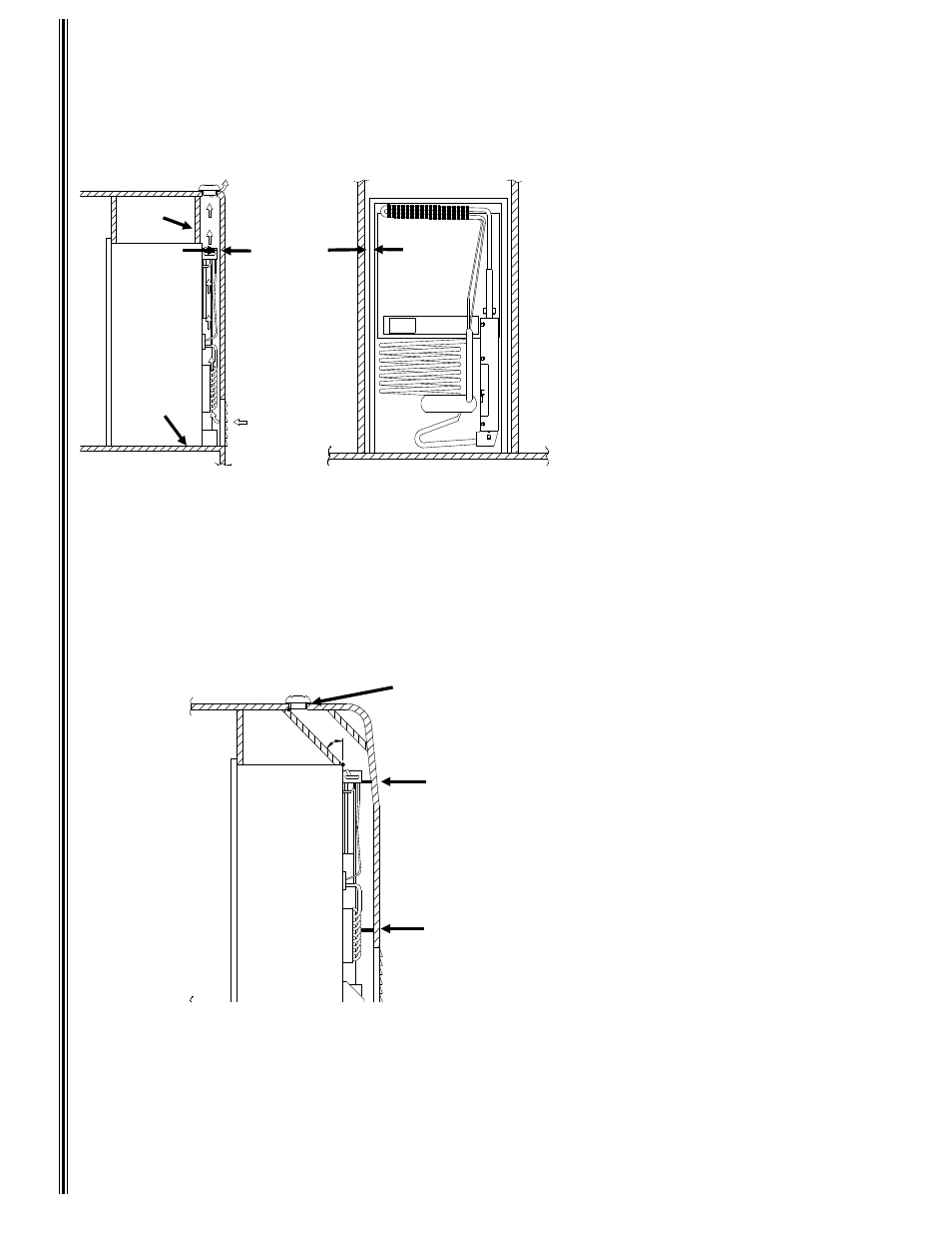
clearances between the refrigerator and any adjacent walls or surfaces are illustrated in Figure 3.
In
stal
latio
n
Requ
iremen
ts
Figure 3
Optimum Clearance
Requirements
•
Minimum clearances between the re-
frigerator and all adjacent walls and
surfaces:
(A) 0 - 1/4 inch at the top of the re
refrigerator
(B) 0 - 1/2 inch at the sides of the
refrigerator
Note: Side clearances in
excess of 1/2 inch must
be either filled with fiber-
glass batting or blocked with
paneling, etc.
(C) O-1 inch at the rear of refrigerator
(D) 0 inches at the bottom of the re-
refrigerator
The combination of the two vents and the clearances
defined provide the necessary air flow through the
creation of a natural draft, or "chimney effect," across
the cooling system.
Air Flow
D
C
B
A
Figure 4
A
Alternate Construction
Requirements
•
Exhaust (upper) vent opening (A) is
inboard in relation to the rear of the
refrigerator
•
Baffles (B) added to top of refrigerator
to assist in directing air flow out the
exhaust vent
•
Angle between baffles (B) and rear top
edge of the refrigerator not to exceed
45 degrees
•
Deflectors (C) added at rear locations
adjacent to the cooling unit condenser
and absorber coils to reduce clear-
ance to 1 inch max.
•
Side clearances are the same as illus-
trated in Figure 3
B
B
C
C
6