Flame failure safety device check, Hypot test, Lighting instructions and diagnostics – Thetford 9100 Series Installation Manual User Manual
Page 10: Lighting instructions - 900 series
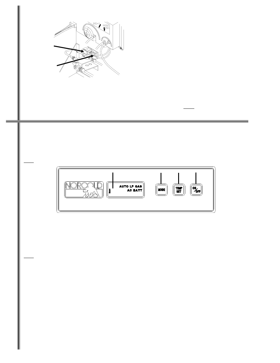
Flame Failure Safety Device Check
Out
The purpose of the gas safety device is to prevent
escape of unburned gas from burner if the burner
flame is extinguished. While there is a flame pre-
sent at burner, disconnect one wire from gas sole-
noid valve located at rear of refrigerator. Within 30
seconds, flame will go out, indicating the safety
lock-out circuit is operational. Reconnect wire to the
gas solenoid valve upon completion of test.
Hypot Test
A Dielectric Strength test (hypot) has been conducted at the factory; this refrigerator does not require an additional
test. If hypot tests are conducted on the vehicle’s 12 volt circuit, the 12 volts must be disconnected from the
refrigerator to protect the flame ignition circuit.
Lighting Instructions - 900 Series
Note
: 12 volt DC must be available for both the Auto and Manual modes.
1. Auto Mode - Push ON/OFF button (D) to start refrigerator in fully automatic mode. Push SET POINT
(thermostat) button (B) to a mid range setting. If 120 volt AC is available, AUTO AC will be visible in center display
window (A), indicating AC operation. If 120 volt AC is not available, AUTO LP GAS will be visible in center display
window, indicating LP Gas operation.
2. Manual Mode - Push ON/OFF button (D) to start refrigerator, press and hold mode selection button until LP GAS
is visible in center display window. Push SET POINT (thermostat) button (C) to a mid range setting.
Note
: If the gas does not ignite within 30 seconds, the refrigerator’s gas valve will automatically close
and the operating controls will revert to a stand-by mode in which an alarm will sound and the
code "A1" will be displayed in the center display window. If the gas does not ignite after several
attempts, refer to "Diagnostic Codes and Their Meanings" on page 10 for corrective actions.
3. To turn refrigerator "OFF", push and hold "ON/OFF" button (D) for 2 seconds.
A
C
B
D
Figure 10
Gas Solenoid
Valve
Remove wire
from valve
L
ig
h
ti
ng
I
n
structio
ns &
Diagn
o
stics
In
stal
latio
n
Requ
iremen
ts
10