Laser calibration / maintenance – Symtech SCA 1 User Manual
Page 8
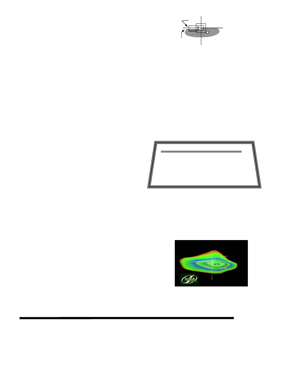
H
V
US Low Beam
VOL
.4 Degree Down
(2.096 Inches)
Aim Area
8
•
SAE LOW BEAM “
VOL
” (Visual Optical Left):
Low beam lamps manufactured after 1999, some
vehicles. The high intensity area is located in the
lower right hand quadrant and the beam pattern is
aligned by placing the left upper portion of the beam
pattern on the .4 Degree (2.096”) Down Horizontal
axis.
•
HID (High Intensity Discharge / Xenon) Lamps
Some HID / Xenon lamps (bright and bluish in appearance) generate
minimal Infrared emission to activate the ISOColor screen, visual
appearance of pattern on screen may have only one color and possibly
no color. However, a representative visual alignment is achieved by
observing the lamp pattern as depicted on the screen and aligning it to
the appropriate position. In the event of only one, or two colors
appearing on screen, the center of the inner most color represents the
hot spot.
4.4 ALIGNMENT OF HEADLAMP PROCEDURE
1.
Locate SCA 1
ISOColor approximately 12 inches from in
front of the lamp to be aligned. Placement can be 6” to 18”
without jeopardizing alignment.
1. Position “SCA 1” in Front of first
lamp to be Aligned.
2. Adjust Floor Slope to Recorded
Bay Setting.
3. Square SCA 1 to Vehicle by
Looking Trough Sighting Unit.
Headlamp Alignment Procedure
4. Aligning Two Common Points with
Line in Sighting Mirror.
5. Select Lamp Beam Type. While
viewing Lamp Patten, Adjust
Lamp to Pictorial Position
6. Move SCA 1 to Next Lamp and
Repeat Steps 3 Through 5.
2.
Position SCA 1
ISOColor in front of first lamp to be
aligned. Centering of system on headlamp is very
forgiving, as the fresnel lens provides a
± 1.5” widow for
centering.
3.
Align SCA 1
ISOColor to vehicle by sighting through the
sighting unit and rotating optical head until line in sighting
unit intersects the two common points selected.
4.
Headlamps should be switched on to low beam as this is
the primary driving lamp.
a.
In compound lamps, where the Low Beam and
the High Beam are in the same lamp, you only
align one pattern, as by law, the other pattern
must be within 1.5” of perfect alignment.
5.
While viewing aim screen, adjust headlamp to position that
appears as graphic illustration of headlamp pattern selected.
The most inner portion of color is the high intensity zone
and this is what you center over the white dot designated
for the lamp pattern selected.
i. NOTE: Graphics on aiming screen
denote position of lamp position in
inches.
ii. Outer box denotes 8 inches, inner box
denotes 4 inches. Each hash mark
denotes 1 inch increment.
6.
Repeat steps for remaining lamps.
5. LASER CALIBRATION / MAINTENANCE
5.1 FLOOR SLOPE LASER CALIBRATION
“LASER IS CALIBRATED AT THE FACTORY PRIOR TO SHIPMENT”