R s p - 1 0 0 0, 1000w single output power supply, Function description of cn50 function manual – ProgressiveRC RSP-1000 series User Manual
Page 3
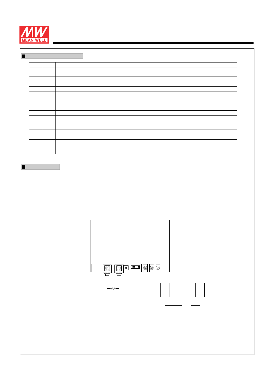
TB1
Fig 1.1
LOAD
-
+
SVR51 CN50
1 11
2 12
-V
+V
The power supply unit will have no output if the shorting connector (accessory comes along with the PSU) is not assembled. It contains
two shorting wires : one is from ON/OFF (pin6) to -S (pin2) and the other is from Vco (pin8) to Vca (pin10).
+S
1
-S
2
AUXG
AUX
DC_OK
ON/OFF
CS
CN50
(Shorting connector)
Vco
Vci
Vca
GND
11
GND
12
1000W Single Output Power Supply
R S P - 1 0 0 0
s e r i e s
Function Description of CN50
Function Manual
1."Remote ON/OFF" and "Output voltage trim" functions are not used.
Pin No. Function Description
1
4
5
7
8
10
11,12
2
3
6
9
+S
5V-AUX
DC_OK
CS
Vco
Vca
GND
-S
G-AUX
ON/OFF
Vci
Auxiliary voltage output, 4.6~5.25V, referenced to pin 3(G-AUX). The maximum load current is 0.5A. This output has the built-in oring
diodes and is not controlled by the "remote ON/OFF control".
Open collector signal, referenced to pin11,12(GND). Low when PSU turns on. The maximum sink current is 10mA and the maximum
external voltage is 5.6V.
Current sharing signal. When units are connected in parallel, the CS pins of the units should be connected to allow current balance
between units.
Short connecting between Vco (pin8) and Vca (pin10) if output voltage trim function is not used.
Connect to external resistor (1/8W) for output voltage triming. Output voltage can be trimmed between 40 ~ 110% of the rated output
voltage. Please refer to function manual for details.
These pins connect to the negative terminal (-V). Return for DC_OK Signal output.
Turns the output on and off by electrical or dry contact between pin 6 ( ON/OFF) and pin 2 (-S). Short: Power ON, Open: Power OFF.
Connect to external DC voltage source for output voltage triming, referenced to pin 2 (-S). Output voltage can be trimmed between
40 ~ 110% of the rated output voltage.
Negative sensing. The -S signal should be connected to the negative terminal of the load. The -S and +S leads should be twisted in pair to
minimize noise pick-up effect. The maximum line drop compensation is 0.5V.
Positive sensing. The +S signal should be connected to the positive terminal of the load. The +S and -S leads should be twisted in pair to
minimize noise pick-up effect. The maximum line drop compensation is 0.5V.
Auxiliary voltage output ground. The signal return is isolated from the output terminals (+V & -V).
File Name:RSP-1000-SPEC 2008-01-22