1 special hints, Ktlx800/pitx software guide, 1 reserved bits – Kontron KTLX800-pITX User Manual
Page 16: 2 gpio input register
KTD-S0023-A
Page 13
CPLD Interface
KTLX800/pITX Software Guide
The GPIO registers represent an exception. The access is executed with linear addressing and 16 bit data
width (fixed addresses).
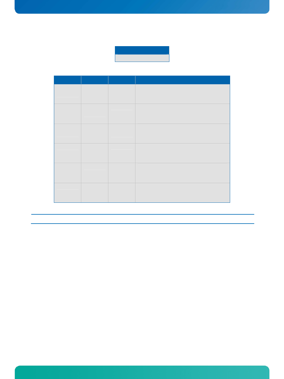
Register Range
0xB00 - 0xB0B
Register overview:
Offset
Type
Reset
Function
0x00
RO
---
GPIO data input register
Bit 0 = GPIO0 ... Bit 15 = GPIO15
0 = define low input
1 = define high input
0x02
RW
0x0000
1)
GPIO data output register
Bit 0 = GPIO0 ... Bit 15 = GPIO15
0 = define low output
1 = define high output
0x04
RW
0x0000
1)
GPIO data direction register
Bit 0 = GPIO0 ... Bit 15 = GPIO15
0 = define input
1 = define output
0x06
RW
0x0000
1)
GPIO tri-state register
Bit 0 = GPIO0 ... Bit 15 = GPIO15
0 = normal output
1 = tri-state output
0x08
RW
0x0000
1)
GPIO interrupt polarity register
Bit 0 = GPIO0 ... Bit 15 = GPIO15
0 = falling edge
1 = rising edge
0x0A
RW
0x0000
1)
GPIO interrupt register
Bit 0 = GPIO0 ... Bit 15 = GPIO15
0 = interrupt disabled
1 = interrupt enabled
Note:
1)
Default Setup settings.
5.1
Special Hints
The following remarks must be considered (especically the first hint).
5.1.1 Reserved
Bits
Every bit which is marked as
Reserved may not be changed. Not observing this hint can in the worst case
lead to system crashes, e.g. after a warm boot.
5.1.2 GPIO
Input
Register
The input register reflects the status of the pins which are defined as output. Example: if GPIO7 defined as
an output the GPIO7 bit in the input register reads back low level when the output has low level and a high
level when the output has high level.