Installation, 1 general, Installation - 3 – Kontron OM6040 Compact User Manual
Page 35: 1 general - 3, Om6040 base solution configuration - 3, Installation om6040
ID 1027-6427, Rev. 2.0
Installation
OM6040
Page 3 - 3
3.
Installation
3.1
General
The OM6040 shelf itself is an application support platform for MicroTCA™ solutions. In order
to satisfy solution requirements it must be configured accordingly. To assist application devel-
opers and system implementers in achieving their goals, the OM6040 is provided with a mini-
mum configuration. Specifically, it is delivered with an appropriate MCH module.
The following table and figures illustrate the base solution configuration of the OM6040. This
configuration is the basis for the information and procedures provided in the following Installa-
tion sections.
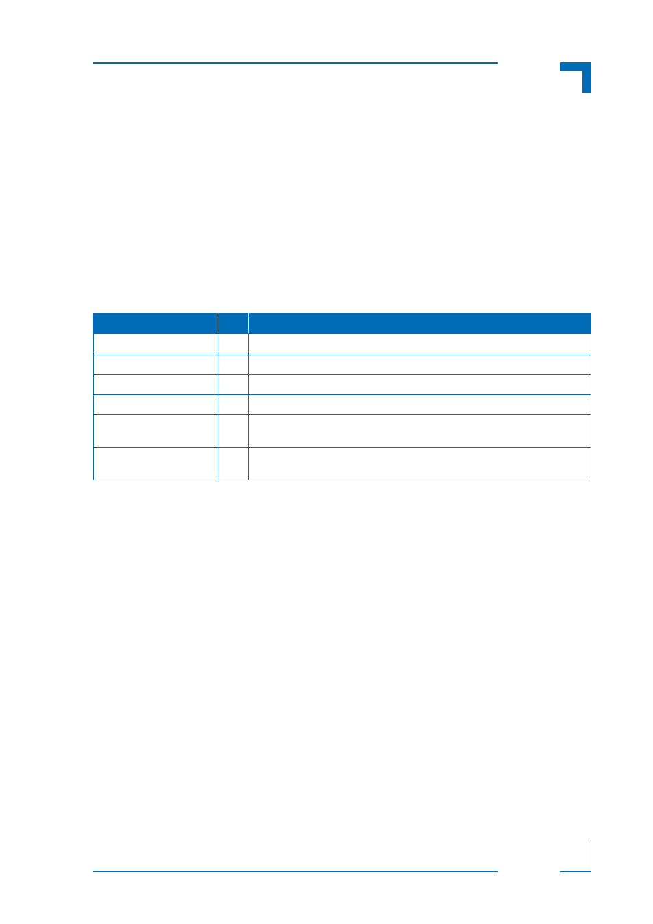
Legend for Table 3-1:
FSA = front slot area, as seen from front - numbered left to right
QTY = quantity
Table 3-1: OM6040 Base Solution Configuration
COMPONENT
QTY
SYSTEM LOCATION - DESCRIPTION
Subrack
1
Mechanical chassis of OM6040
Backplane
1
-
Power Supply Unit (PSU)
1
Built-in to the rear bay area
Fan
2
One fan in the bottom-front bay area, and one fan in the rear bay area
Filler Panels
0
Must be ordered separately as required. Available are 2HP filler panels and
Full-size dummies
MCH
1
FSA-5: Single Full-size with extraction handle
Required configuration must be specified at time OM6040 is ordered