Add2-crt, Functional diagram, Connector/cable kit descriptions – Kontron KTD-00735 ADD2-CRT User Manual
Page 6
ADD2-CRT
KTD-00735-C
Public User Manual
Date: 2009-05-18
Page
6 of 7
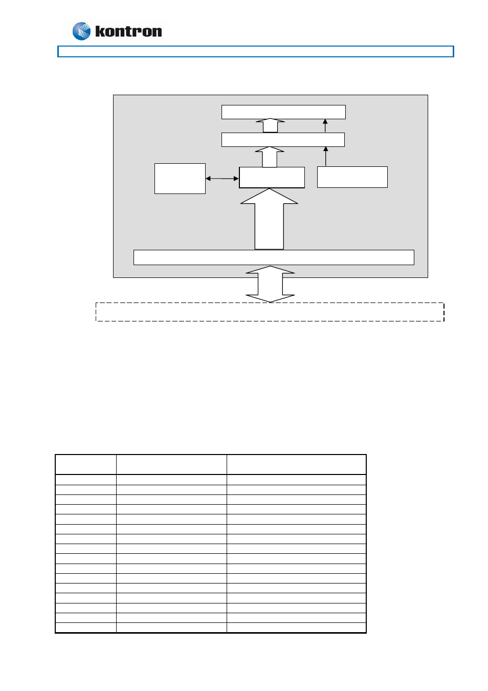
Functional Diagram
Note that VBIOS located in I2C is not used as default. The reason is that the BIOS used in the Kontron
Motherboards of 986LCD-M and KT965 families are supporting the ADD2-DVI card directly.
Connector/Cable kit descriptions
The 821516 CRT Bracket cable kit is 140mm long and is based on a pin socket connector (16 terminals) and
a HDDB15 standard VGA CRT connector. Optionally the ADD2-CRT card has a HDDB15 connector (J4)
having the same pinning as the cable kit HDDB15 connector.
821516 cable wiring:
Pin-Row J3
HDDB15 J4 and cable kit
Pin No.
Pin No.
Signal
1 11
NC
2 15
DDC
Clock
3 10
GND
4 8
GND
5 14
Vsync
6 4
NC
7 9
+5V
(55mA)
8 13
Hsync
9 3
Blue
10 7
GND
11 12
DDC
Data
12 2
Green
13 6
GND
14 -
NC
15 1
Red
16 5
GND
PCI-Expressx16 connector
Motherboard with multiplexed PCI-Expressx16/SDVO connector
SDVO to CRT
Converter #1
Pin-Row connector J3
VBIOS
I2C PROM
5V Current limited
supply
HDDB15 CRT connector J4 (option)
SDVO
SDVO-B
ADD2-CRT