3 system relevant information, 4 board diagrams, Cp6925 introduction – Kontron CP6925 User Manual
Page 19
Doc.ID: 35008, Rev 1.0
Page 1 - 5
CP6925
Introduction
CUSTOMER SPECIFIC
P R E L I M A R Y
1.3
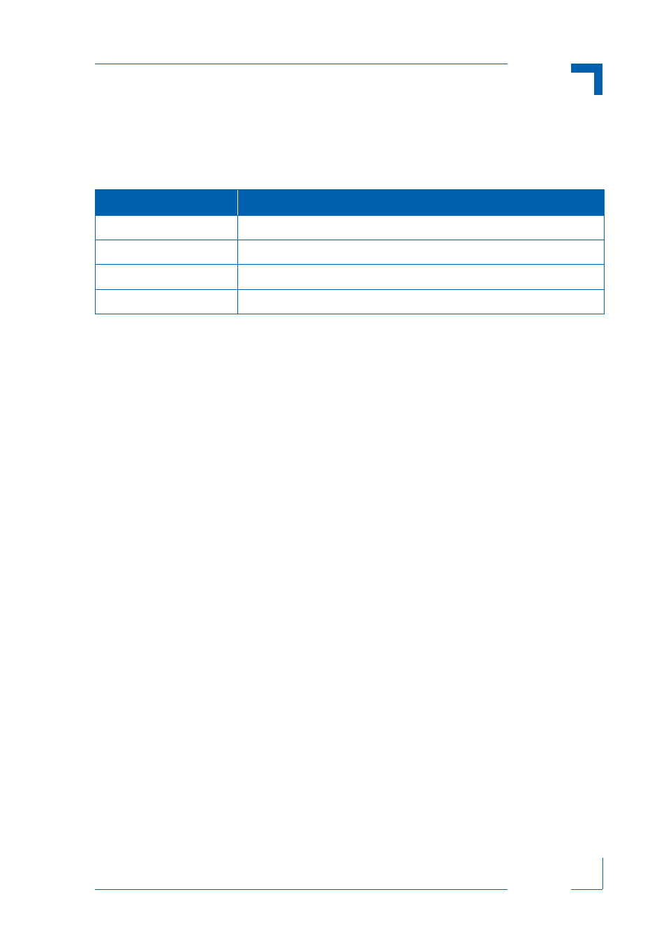
System Relevant Information
The following system relevant information is general in nature but should still be considered
when developing applications using the CP6925.
1.4
Board Diagrams
The following diagrams provide additional information concerning board functionality and com-
ponent layout.
Table 1-1: System Relevant Information
SUBJECT
INFORMATION
System Configuration
The CP6925 may be used in any CompactPCI PICMG 2.16 PSB system.
Board Location in the System
The CP6925 board may only be installed in a fabric slot.
Hot Swap Compatibility
The CP6925 is not Hot Swap capable.
Operating Systems
The CP6925 requires no drivers or operating system support.
LEGEND FOR FIGURES 1-1 to 1-4
BP NODE Backplane node
CPCI CompactPCI
Dnn LEDnn; D1 to D16, paired LEDs
GbE Gigabit Ethernet
GbE SW Gigabit Ethernet Switch
Jn Connector number n; J1, J3, J5, J6A/B
LPnn Link port nn; LP01 to LP14
MAG Magnetic
nn Ethernet channel number nn; 15 and 16
PSB Packet Switching Backplane
RX Receive
TSE Three Speed Ethernet; 10/100/1000 Mbits/s
TX Transmit
TXRX Transceiver