Inst-digmanifoldpg3, Charging by the subcooling method, Systems with txv and no receiver – Just Better DM-2 Digital Manifold User Manual
Page 3: Scroll low side scroll high side, Push for avg. hold to clr
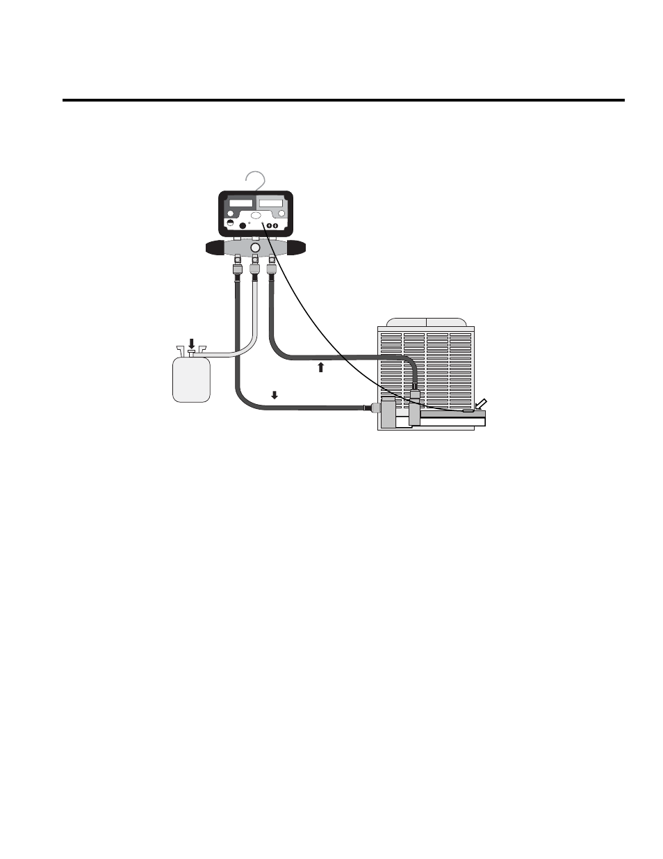
1. Connect the Manifold to the system as shown with the T2 temperature sensor installed on the liquid line.
2. Select the system refrigerant by pushing the refrigerant button of the Manifold until the required refrigerant is shown in the
right side display.
3. Put the right side display in the Subcooling mode by toggling the Scroll High Side button.
4. Determine the required subcooling for the system as recommended by the manufacturer or wholesaler. 10˚F - 12˚F are
typical values.
5. Very slowly add or remove refrigerant until the Manifold displays the required subcooling.
CHARGING BY THE SUBCOOLING METHOD
Designed For:
13 SEER and other High efficiency Air Conditioning Systems
Large Commercial A/C Rooftop Packages
Refrigeration Systems
13 SEER high efficiency air conditioning systems equipped with a TXV expansion device require a minimum subcooling value to
insure solid liquid at the expansion valve. These systems often use the bottom tubes of the condenser as a refrigerant receiver.
As a result the amount of refrigerant charge is critical. Too much charge will result in high head pressures during summer
operation. Too little charge will cause flash gas in the liquid line and reduce cooling ability.
Pipe as shown with a temperature sensor on the liquid line. Toggle to Subcooling using the Scroll High Side button to display the
subcooling value. Very slowly add or remove refrigerant to obtain the manufacturers target subcooling value. Allow the system
to stabilize for 20 minutes after adding or removing refrigerant charge before retesting for subcooling.
Many manufacturers use 10°F subcooling as an acceptable value but the actual subcooling value must take into account the fact
that the liquid refrigerant at the TXV must be solid liquid. The liquid line vertical rise and the long liquid line runs will also affect
the required subcooling. See the system manufacturers instructions for the amount of subcooling required to compensate for
these installation situations.
SYSTEMS WITH TXV AND NO RECEIVER
CONDENSING
UNIT
TEMPERATURE
SENSOR
LIQUID LINE
SUCTION LINE
REFRIGERANT
TANK
QC RESTRICTOR
FITTING
TO SUCTION
SERVICE VALVE
TO LIQUID LINE
SERVICE VALVE
SCROLL
LOW
SIDE
SCROLL
HIGH
SIDE
REFRIGERANTS
T1
T2
ON/
OFF
PUSH
FOR
AVG.
HOLD TO
CLR
JB
PLUG INTO T2 JACK
FOR SUBCOOLING